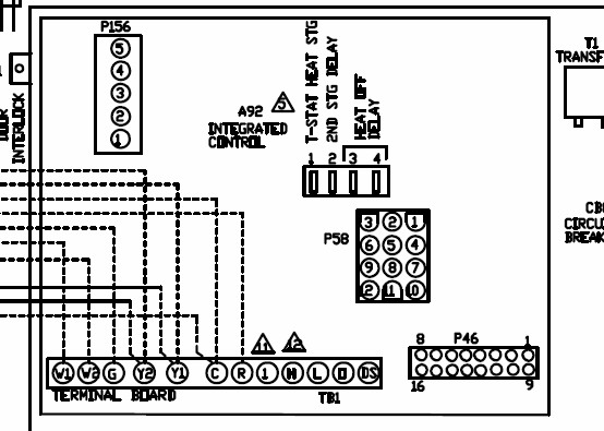
provides the installation procedures, wiring diagrams, DIP switch settings, etc .. SIGA-CC1S, Genesis G1M-RM, FireShield panel, or a BPS generating Genesis. siga cc1s wiring diagram – A Novice s Guide to Circuit Diagrams.
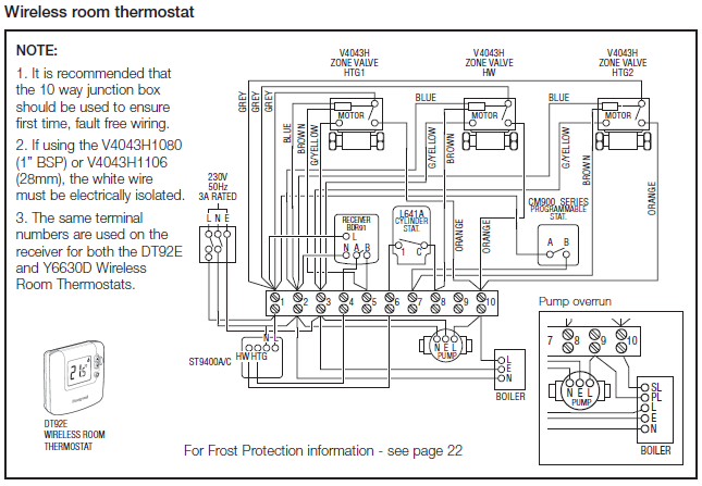
An initial take a look at a circuit diagram could be complex, yet if you can read. circuit.
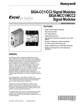
The actual operation of the SIGA-CC1/MCC1 and. SIGA-CC2/MCC2 is determined by the selected “personality .
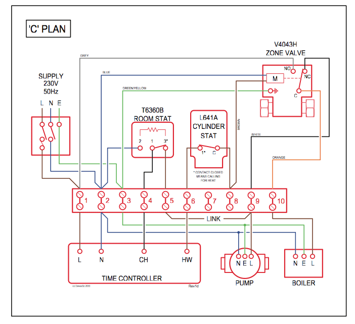
See diagram on the following page. GSA-CC1 Single Input Signal Module Installation Sheet. P/N PEN . Figure 3: Wiring diagram for NAC (personality code 5).
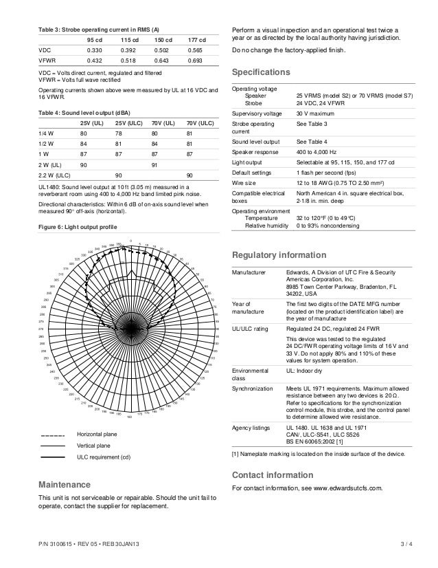
(1) Signal polarity is. Addressable analog circuit wire length • B Cabinet battery • B. .

diagrams and descriptions of specific access control systems. Chapter 4.A wiring diagram is a simple visual representation of the physical connections and physical layout of an electrical system or circuit. It shows how the electrical wires are interconnected and can also show where fixtures and components may be connected to the system.
See diagram on the following page. Signal (Slave) Circuit Wire Specifications Maximum Allowable Wire Resistance (valid maximum limit with no load on the circuit) 50 ohms (25 ohms per wire) per circuit Maximum Allowable Wire Capacitance µF per circuit.
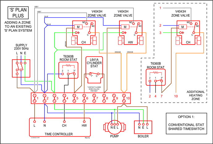
SIGA-CR – Control Relay Module 1 / 4 SIGA-CR Control Relay Module Product description 4 3 2 1 8 7 6 The SIGA-CR Control Relay Module is a component of the Make all wiring connections as shown in the wiring diagram. 3.
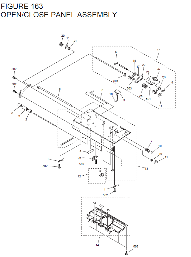
Write the address assigned to the module on the label provided and apply the label to the module. Peel off the.
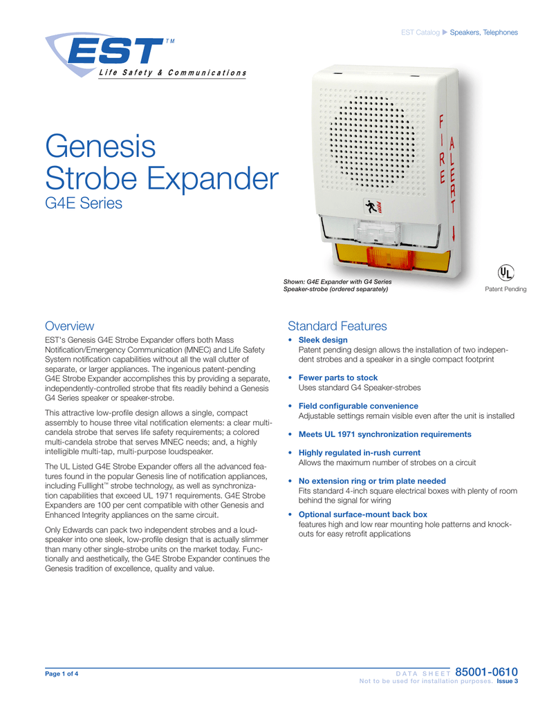
G1RT-FIRE MG1RT-FIRE XLSG1RT-FIRE ZG1RT-FIRE Auto-Sync Output Module SIGA-CC1S SIGA-MCC1S Figure 3: Wiring diagram 1 2-+ 1. From compatible fire alarm control panel 2.
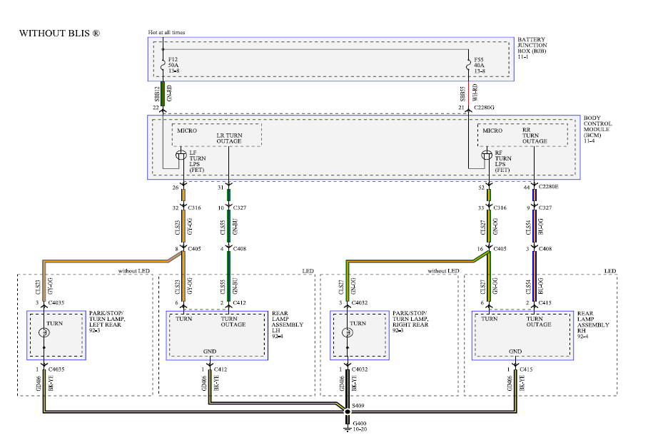
To next appliance, EOL, or return to source Note: Polarity is shown in the alarm condition. Siga Cc1S Wiring Diagram – here you are at our site. Today we are pleased to declare that we have discovered an incredibly interesting niche to be pointed out, namely siga cc1s wiring schematron.org people looking for specifics of siga cc1s wiring diagram and certainly one of these is you, is not it?Data Sheet — Synchronization Output Module14 Plus Siga Cc1S Wiring Diagram Photograph | Wiring Diagram Reference
