
CDI (Capacitor Discharge Ignition) is an electronic ignition system used in many modern two-wheeler and four-wheeler vehicles. It is a high-energy ignition system that produces a powerful spark to ignite the air-fuel mixture in the engine’s combustion chamber. CDI ignition systems offer several advantages over traditional ignition systems, including improved starting performance, increased fuel efficiency, and reduced emission levels.
The schematic diagram of a CDI ignition system consists of several main components, including the ignition coil, capacitor, diode, triggering circuit, and timing circuit. The ignition coil is responsible for generating a high voltage current that is required to produce a spark. The capacitor stores electrical energy and releases it in a quick burst to create a powerful spark. The diode prevents reverse current flow and protects the transistor from damage.
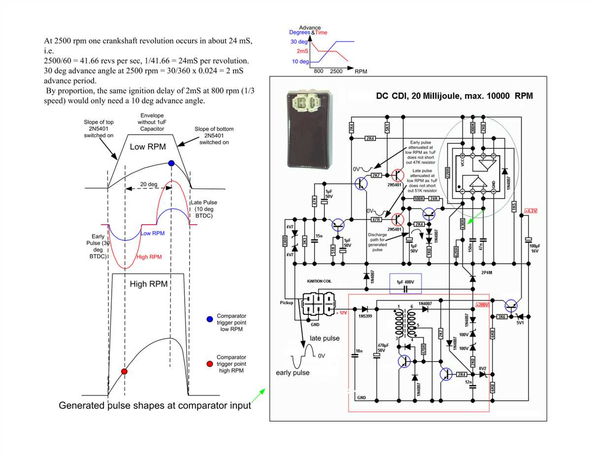
The triggering circuit is responsible for sensing the engine’s position and triggering the spark at the right moment. It typically consists of a pickup coil, a trigger rotor, and an electronic control unit (ECU). The pickup coil generates an AC voltage pulse as the trigger rotor passes by, and the ECU processes this signal to determine the timing of the spark. The timing circuit adjusts the timing of the spark based on various factors, such as engine speed, throttle position, and temperature.
In summary, a CDI ignition system is a complex electronic system that uses a combination of components and circuits to generate a powerful spark for igniting the air-fuel mixture in the engine’s combustion chamber. It offers many advantages over traditional ignition systems and is widely used in modern vehicles for its improved performance and efficiency.
CDI Ignition Schematic
A CDI (Capacitor Discharge Ignition) ignition system is a type of ignition system commonly used in motorcycles and small engines. It is known for its high energy output and reliable performance. The CDI ignition system uses a capacitor to store energy and discharge it rapidly to the ignition coil, creating a high-voltage spark that ignites the air-fuel mixture in the engine.
The basic schematic of a CDI ignition system consists of several key components. These include the ignition coil, capacitor, pulse generator, and CDI unit. The ignition coil is responsible for transforming the low voltage from the battery into a high-voltage spark. The capacitor stores the energy and releases it quickly to the ignition coil. The pulse generator, which is often a pickup coil or Hall effect sensor, detects engine revolutions and sends a signal to the CDI unit to trigger the spark. The CDI unit controls the entire ignition process, including the timing and intensity of the spark.
The CDI ignition schematic can vary depending on the specific design and manufacturer, but the basic principles remain the same. When the engine is running, the pulse generator sends a signal to the CDI unit, which in turn charges the capacitor. Once the capacitor is fully charged, the CDI unit triggers the ignition coil to discharge the stored energy, creating a high-voltage spark at the spark plug. This spark ignites the air-fuel mixture, causing combustion and powering the engine.
Overall, the CDI ignition system offers several advantages over traditional ignition systems. It provides a stronger and more reliable spark, resulting in improved engine performance and fuel efficiency. Additionally, the CDI system is less prone to wear and tear, as it has fewer moving parts compared to other ignition systems. It is also more resistant to environmental factors such as moisture and temperature fluctuations. These advantages make the CDI ignition system a popular choice for many small engines and motorcycles.
Diagram:
|
|

What is CDI Ignition?
The Capacitor Discharge Ignition (CDI) system is a type of ignition system used in internal combustion engines to ignite the fuel-air mixture. It is commonly found in motorcycles, outboard motors, and some small engines.
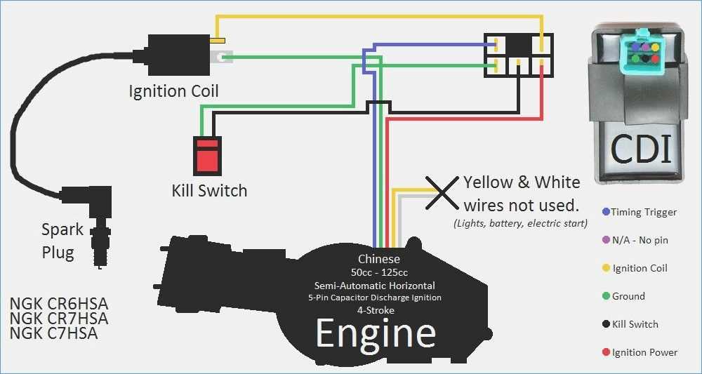
The CDI system consists of several components, including a CDI unit, a charging coil, a high voltage transformer (or ignition coil), and a spark plug. The CDI unit acts as the control center of the system, receiving input signals from the engine’s sensors and delivering high voltage pulses to the spark plug.
Unlike traditional ignition systems that use mechanical contact points, the CDI system relies on solid-state electronics to control the ignition process. It operates in two main stages: charging and discharging. During the charging stage, the charging coil generates electrical energy, which is stored in a capacitor. When the input signals from the engine’s sensors indicate the need for ignition, the CDI unit triggers the discharge stage, whereby the stored energy in the capacitor is rapidly released to the ignition coil.
This rapid discharge creates a high voltage pulse that is sent to the spark plug. The spark plug then generates an electric spark that ignites the fuel-air mixture in the engine’s combustion chamber, resulting in the power stroke of the engine.
CDI ignition systems offer several advantages over traditional ignition systems, including improved reliability, higher energy output, and faster spark development. These systems also provide better control over the ignition timing, allowing for optimal engine performance and fuel efficiency.
Working Principle of CDI Ignition
CDI (Capacitor Discharge Ignition) is an electronic ignition system used in internal combustion engines to improve the ignition process. It is commonly used in motorcycles, ATVs, and small engines. The CDI ignition system works on the principle of storing energy in a capacitor and releasing it to the ignition coil to generate a high voltage spark.
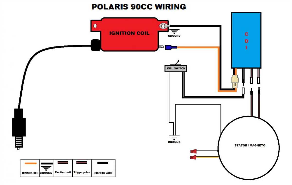
The basic components of a CDI ignition system include a stator, pick-up coil, ignition coil, capacitor, and spark plug. The stator is responsible for generating electrical power that is used to charge the capacitor. The pick-up coil is used to detect the position of the engine crankshaft and send a signal to the CDI unit. The ignition coil transforms the low voltage from the CDI unit into a high voltage spark, which is then delivered to the spark plug for combustion.
The working principle of a CDI ignition system involves several steps. Firstly, the stator generates electrical power as the engine crankshaft rotates. This power is then rectified and stored in the capacitor. The pick-up coil continuously monitors the position of the crankshaft and sends a signal to the CDI unit when the engine is at the desired ignition timing. The CDI unit then triggers the ignition coil to release the stored energy from the capacitor. This energy is transformed into a high voltage spark, which ignites the fuel-air mixture in the combustion chamber.
One of the key advantages of a CDI ignition system is its ability to generate a high voltage spark consistently, regardless of engine speed or load. This results in improved engine performance, better fuel efficiency, and reduced emissions. CDI ignition systems are also more reliable and durable compared to traditional contact point or magneto ignition systems.
Overall, the working principle of a CDI ignition system is based on the efficient storage and release of electrical energy to generate a high voltage spark. By utilizing electronic components, CDI ignition systems offer several benefits over conventional ignition systems and have become widely used in various applications.
Components of CDI Ignition System
The Capacitor Discharge Ignition (CDI) system is a type of ignition system used in internal combustion engines to generate high-voltage electrical sparks for igniting the fuel-air mixture. It consists of several key components that work together to produce a reliable and efficient ignition system.
1. Capacitor: The capacitor is one of the main components of a CDI ignition system. It stores electrical energy and releases it in a rapid and controlled manner. The capacitor is charged by the primary coil of the ignition system and then discharged to the ignition coil when the ignition signal is received.
2. Ignition Coil: The ignition coil is responsible for converting the low-voltage electrical energy from the capacitor into high-voltage electrical sparks. It consists of two coils: the primary coil and the secondary coil. The primary coil is connected to the capacitor and receives the charging voltage, while the secondary coil generates the high voltage required for spark generation.
3. Flywheel: The flywheel is a rotating component connected to the engine’s crankshaft. It serves as a timing reference for the CDI ignition system. The flywheel contains permanent magnets or a magnetic rotor that generates a magnetic field as it rotates. This magnetic field triggers the ignition signal, indicating the right time for spark generation.
4. Trigger Coil: The trigger coil is a small coil located near the flywheel. It senses the magnetic field generated by the flywheel and generates an electrical signal that triggers the discharge of the capacitor. The trigger coil is responsible for accurately timing the ignition spark and ensuring it occurs at the optimal moment during the engine’s combustion cycle.
5. Spark Plug: The spark plug is the final component of the CDI ignition system. It is connected to the secondary coil of the ignition coil and is responsible for producing the actual spark. The spark plug generates a high-voltage electrical arc across its electrodes, which ignites the compressed fuel-air mixture in the engine’s combustion chamber.
Overall, the CDI ignition system is a critical component of internal combustion engines. Its components work together to provide reliable and efficient ignition, ensuring smooth engine operation and optimal fuel combustion.
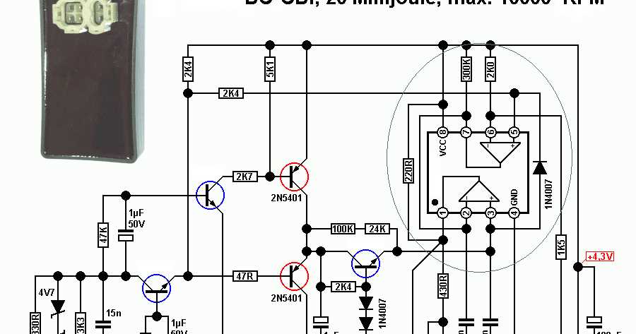
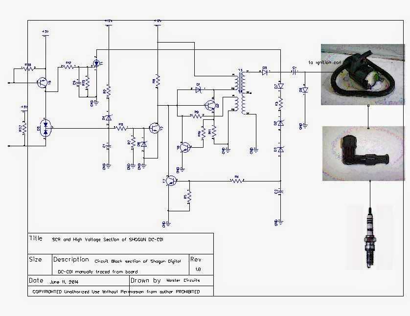
Schematic Diagram of CDI Ignition
CDI (Capacitor Discharge Ignition) is an ignition system used in internal combustion engines. It provides a high-energy spark to ignite the air-fuel mixture in the combustion chamber. The schematic diagram of a typical CDI ignition system consists of several components that work together to generate and deliver the spark.
At the heart of the CDI ignition system is the capacitor, which stores electrical energy. When the engine is running, the charging coil generates an alternating current (AC) that is rectified by a diode to create a pulsating direct current (DC). This DC current charges the capacitor to a high voltage.
The ignition coil is another crucial component of the CDI ignition system. It consists of two windings: the primary winding and the secondary winding. The primary winding is connected to the capacitor, while the secondary winding is connected to the spark plug. When the capacitor is fully charged, a trigger signal from the pulse generator or pickup coil causes the high voltage stored in the capacitor to discharge through the primary winding of the ignition coil.
This sudden discharge of energy creates a magnetic field that quickly collapses, inducing a high voltage in the secondary winding. This high voltage is then delivered to the spark plug, where it jumps the spark plug gap and ignites the air-fuel mixture in the combustion chamber, starting the combustion process.
The CDI ignition system also includes other components, such as a flywheel, pulse generator, and ignition switch, which work together to control the timing and sequence of the spark. Overall, the schematic diagram of a CDI ignition system showcases the sophisticated electrical circuitry involved in generating and delivering a high-energy spark for efficient engine combustion.
Advantages and Disadvantages of CDI Ignition
CDI ignition systems have gained popularity in the automotive industry due to their numerous advantages over conventional ignition systems. However, like any technology, they also have their limitations and disadvantages. In this section, we will discuss the advantages and disadvantages of CDI ignition systems.
Advantages of CDI Ignition:
- Improved Spark Timing: CDI ignition systems provide precise control over spark timing, resulting in improved engine performance and fuel efficiency.
- Stronger Spark: CDI ignition systems produce a stronger spark compared to conventional ignition systems, ensuring better combustion and starting reliability.
- Higher Energy Output: CDI ignition systems generate higher energy sparks, leading to better combustion and increased power output.
- Enhanced Durability: CDI ignition systems have fewer moving parts, reducing the chances of mechanical failure and increasing overall durability.
- Increased Ignition Coil Life: CDI ignition systems put less stress on the ignition coil, resulting in a longer lifespan compared to conventional ignition systems.
Disadvantages of CDI Ignition:
- Higher Cost: CDI ignition systems are generally more expensive to produce and install compared to conventional ignition systems.
- Complexity: CDI ignition systems are more complex and require advanced electronic components and circuitry, making them more challenging to diagnose and repair.
- Compatibility Issues: CDI ignition systems may not be compatible with older vehicles or engines that rely on conventional ignition systems, requiring modifications or retrofitting.
- Electromagnetic Interference: CDI ignition systems can be more susceptible to electromagnetic interference, which can affect their performance and reliability.
- Limited Adjustability: CDI ignition systems may have limited adjustability compared to conventional ignition systems, making it harder to fine-tune the ignition timing for specific engine requirements.
Overall, CDI ignition systems offer several advantages in terms of improved engine performance and reliability. However, they come with certain drawbacks such as increased cost, complexity, and compatibility issues. When considering the use of CDI ignition systems, it is essential to weigh the advantages against the disadvantages and make an informed decision based on the specific requirements of the vehicle or engine.