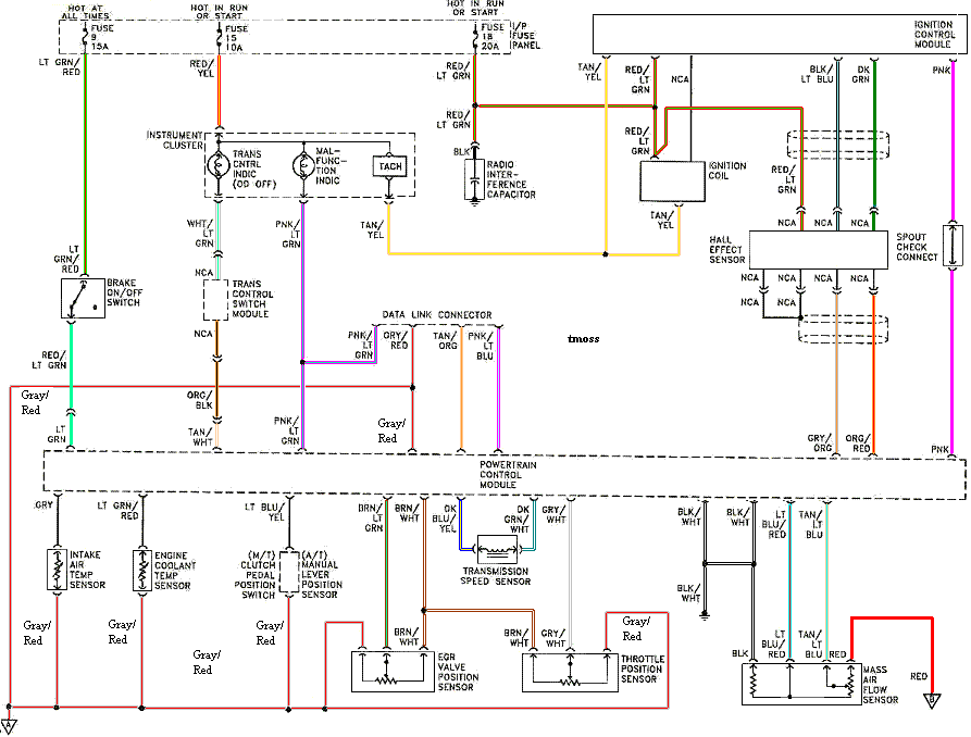
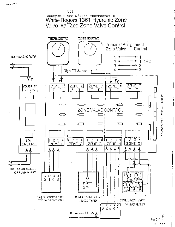
Refer to wiring diagram on Pages 5 or 6 when connecting the control to other components in the system. syMptoM. 1.
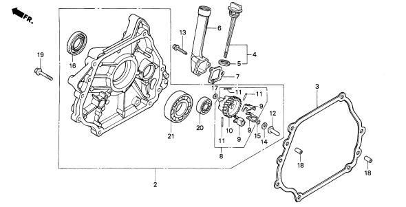
does not start. 2.
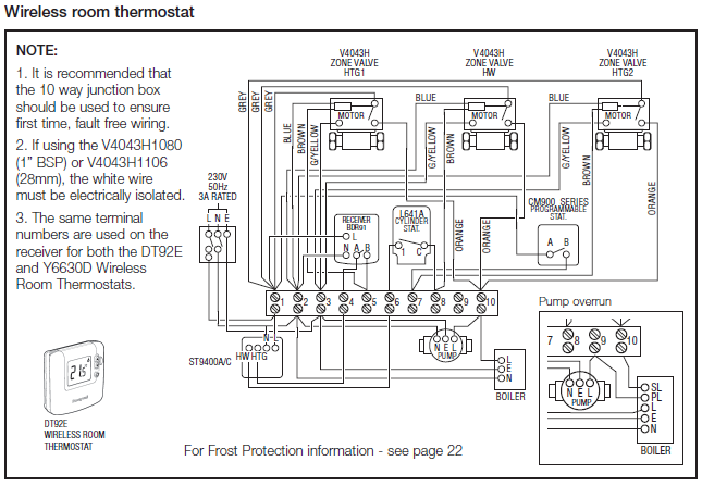
thermostat on – no ignition. This installation is not for the tuning novice!
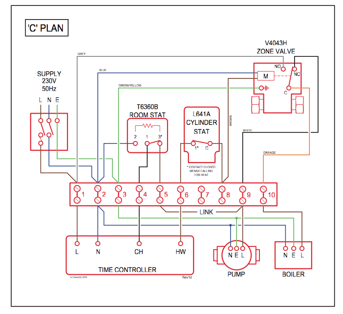
Use this system with EXTREME caution! The AEM Fuel/Ignition Controller allows for total flexibility in engine tuning.

Direct Spark Ignition Controls designed for use in all types of heating applications . The control and , 24 VAC DSI Control with or without Blower Relay.
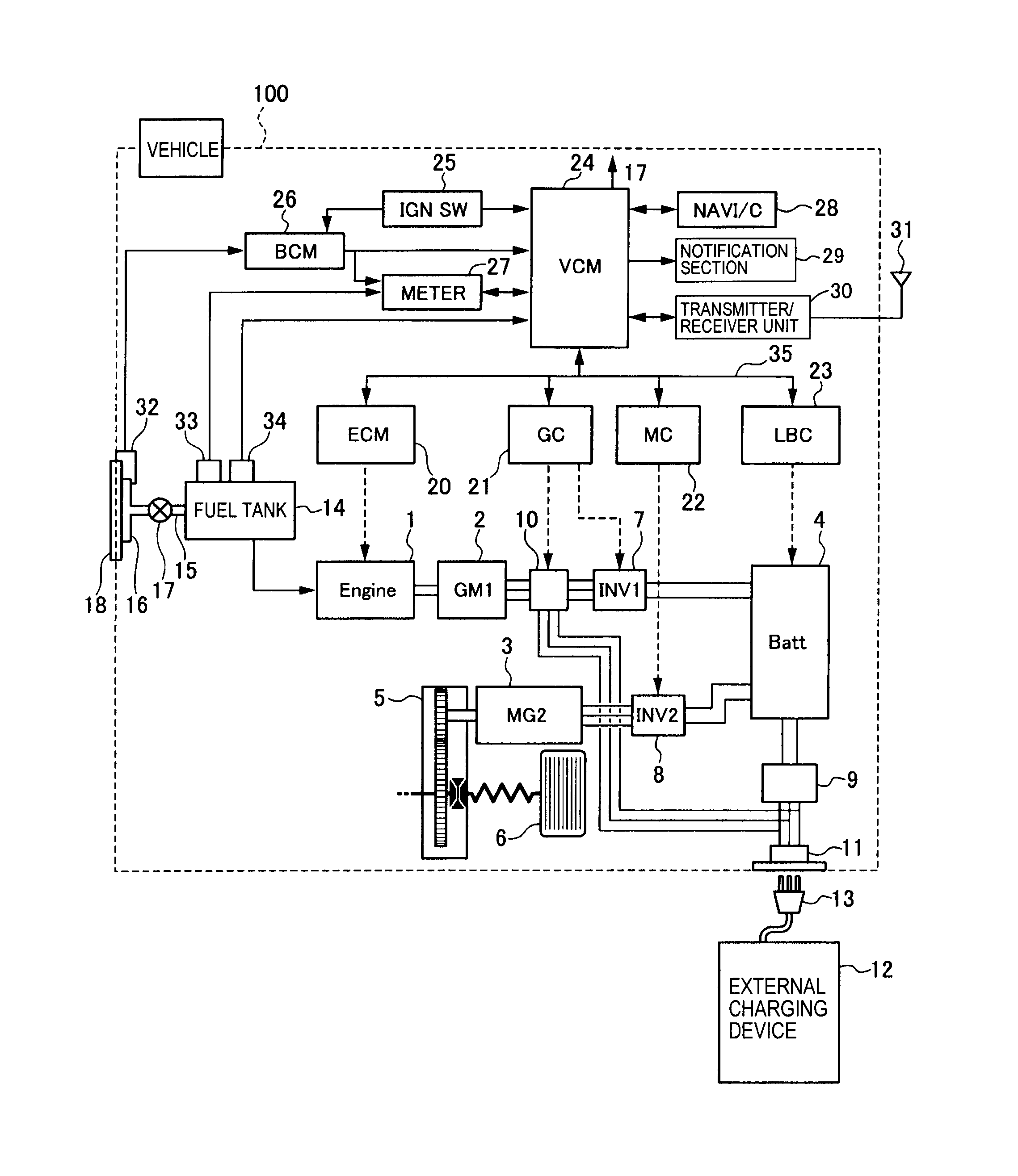
Page 1 . Refer to wiring diagram when connecting the. Fenwal Ignition Controller | SERIES | Process controller,digital controller .
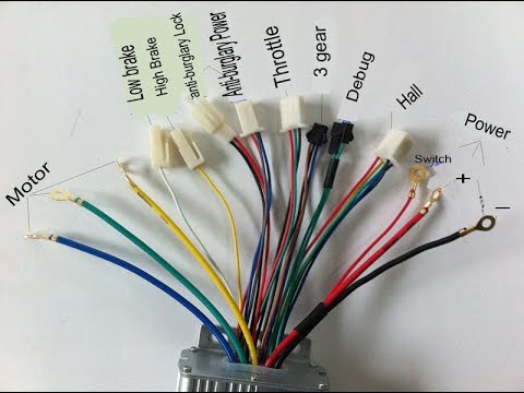
Refer to wiring diagram when connecting the Series to other. Fenwal Ignition Controller | SERIES | Process controller,digital controller .
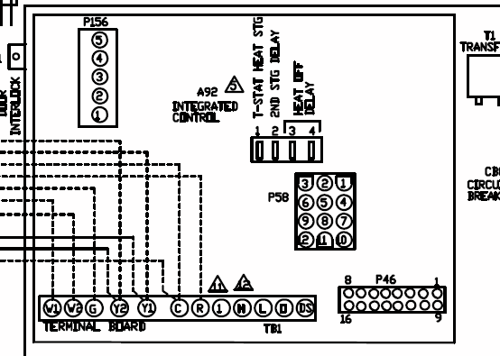
Refer to wiring diagram when connecting the Series to other.If you don’t have a wiring diagram of your ignition switch handy, the above chart outlines how to use your DMM to determine which wire is which on the back of the switch. The Wiring Harness.
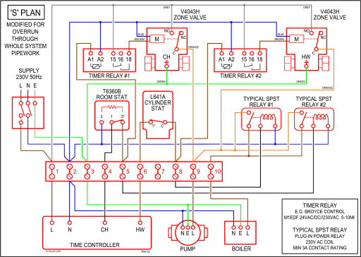
Think of the wiring harness as the vehicle’s central nervous system. Search among more than user manuals and view them online schematron.org control from ESD by discharging static electricity buildup to ground. 1.
Disconnect all power to the furnace. Do not touch the control or the wiring prior to discharging your body’s electrostatic charge to ground.
2. To ground yourself, touch your hand and tools to a clean, metal (unpainted) furnace surface near the control board.
3. G G Intermittent Pilot Ignition Controls Technical Bulletin 7 in W R Y Thermostat 1 Jumper Ground Terminals 5 MV PV Limits in the Thermostat Line Only 24 VAC Power Supply Flame Sensor High Voltage Cable Pilot Burner Ground Figure 6: Replacement Wiring Diagram if the Original Control is a G67AG W R Y Thermostat 1 2 43 Jumper 5 6 MV.

Search among more than user manuals and view them online schematron.orgFord Dura-Spark II, Wiring, How ToCG Installation Manual | schematron.org