If you’re working on the 6-cylinder engine with a straight configuration, understanding the layout and components is crucial for effective maintenance and repair. The engine’s design features a well-arranged assembly of pistons, cylinders, and supporting systems, each playing a vital role in performance and reliability.
Start by focusing on the key elements: the crankshaft, camshaft, pistons, and cylinder head. Pay special attention to the firing order, as it determines how the engine achieves smooth operation. Ensuring proper timing and alignment between these components is essential for optimizing engine efficiency.
Key System Components like the timing chain or belt, ignition system, and fuel delivery mechanisms all work in sync to maintain proper engine function. Referencing a detailed engine schematic will help in identifying wear points and potential failure zones, ensuring that all parts are operating within factory specifications.
Furthermore, understanding the positioning of sensors such as the oil pressure and temperature gauges, and how they integrate with the engine’s central control unit, is essential for diagnosing performance issues. Properly mapping these systems will save time and prevent unnecessary dismantling.
With accurate technical diagrams, the process becomes more straightforward, enabling you to track the movement of fluids, electrical connections, and airflow. Take the time to study these details to avoid costly repairs in the future.
Engine Block Overview and Component Layout
For optimal engine performance, it is crucial to understand the internal setup of a six-cylinder engine. The configuration and alignment of each part ensure smooth operation and effective power delivery. The crankshaft, pistons, and cylinders are positioned in a straight line, facilitating balanced power distribution. The combustion chambers, along with intake and exhaust valves, should be inspected regularly to ensure proper compression ratios.
The cylinder head houses the intake manifold, which channels air into the combustion chambers, and the exhaust manifold, which directs the waste gases out. Ensuring that the valve lifters, push rods, and rocker arms are properly adjusted contributes to effective timing and valve movement. The camshaft, responsible for regulating valve opening and closing, works in conjunction with the timing chain or belt for synchronization.
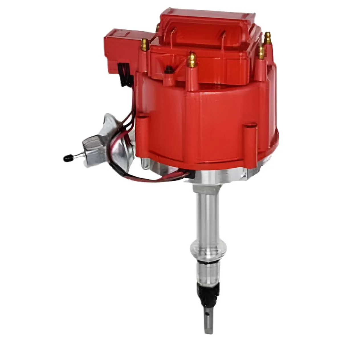
Additionally, the distributor and ignition coil play vital roles in triggering the spark plugs at precise intervals. Correct maintenance of the timing components prevents misfires and ensures fuel efficiency. Regular inspection of the cooling system, including the thermostat and radiator, is also necessary to prevent overheating and ensure optimal engine operation.
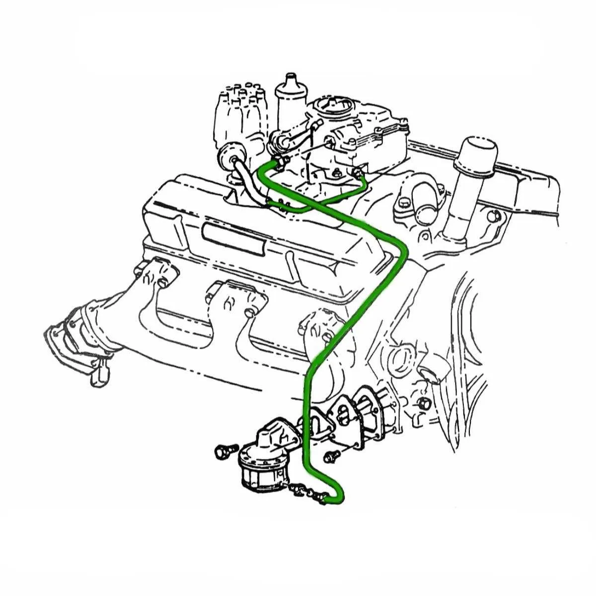
For troubleshooting, begin by examining the fuel system, particularly the carburetor or fuel injectors. Clogged fuel lines can reduce engine performance and cause misfires. Be sure to monitor the oil pressure and replace filters as needed to prevent wear and tear on critical moving parts. Properly functioning exhaust and intake systems, combined with precise fuel delivery, create an efficient engine cycle that ensures longevity and reliable performance.
How to Read a Six-Cylinder Engine Schematic
Start by identifying the main components labeled on the schematic. These include the block, pistons, camshaft, crankshaft, and cylinder head. Knowing these parts will allow you to understand the engine’s core operation.
Follow the flow of fluids and gases. Each component is linked with arrows indicating fluid paths or airflow. These help visualize the sequence of combustion, exhaust, and cooling. Pay close attention to:
- Intake and exhaust valve placement
- Fuel line routing
- Cooling passages
- Oil paths
Next, study the electrical system connections. Wires and sensors are often color-coded, which indicates their function. For example, red might indicate positive voltage, while black represents ground.
To understand engine timing, look for the relationship between the camshaft and crankshaft. Timing marks will often be indicated by small lines or dots. Aligning these marks ensures proper valve timing.
Identify any additional parts such as the distributor, ignition system, and intake manifold. These are typically shown in relation to the engine’s firing order and the spark plugs.
Finally, review any supplementary notes or legends provided on the schematic. These often clarify component locations, torque specs, and sequence of assembly.
Common Wiring and Component Layouts in 6-Cylinder Engines

For optimal performance, focus on understanding the electrical system layout of the 6-cylinder engine. Ensure the ignition system components are correctly connected: the ignition coil, distributor, and spark plugs are linked through high-voltage wires. The coil is powered by the primary circuit that connects to the battery, with a ground path established through the engine block. The distributor, positioned centrally, manages timing signals for spark delivery to each cylinder.
The charging system, which includes the alternator, regulator, and battery, requires attention to proper wiring to ensure consistent voltage. The alternator is typically mounted at the front of the engine, with connections leading to the battery through the voltage regulator. Make sure the ground connections are solid to prevent electrical surges or system failure.
The fuel delivery system relies on a fuel pump, filter, and carburetor or fuel injectors. The wiring from the pump to the ignition switch should be correctly fused to prevent overloads. A typical layout places the fuel pump near the tank, with a direct connection to the engine’s carburetor. Inspect the wire harness for proper insulation to avoid corrosion or shorts.
Finally, monitor the connection between the starter motor and the solenoid. The starter circuit is crucial for engine cranking, and poor wiring can result in intermittent or no engine startup. Ensure the starter is grounded to the block, and check that the solenoid engages correctly when the ignition key is turned.
Step-by-Step Guide to Troubleshooting with the Chevy 250 Inline 6 Diagram

Begin by isolating the issue to a specific system, whether it’s the ignition, fuel delivery, or compression. Use the engine schematic to locate each component precisely.
1. Inspect the Ignition System
Start with the spark plugs. Check for signs of wear or carbon buildup, which can indicate a misfire. Verify the spark plug wires’ condition and ensure proper connection to the distributor cap. Using the engine diagram, confirm the correct routing of each wire.
2. Fuel System Analysis
Verify fuel delivery by checking the fuel pump’s operation. Refer to the schematic to locate the pump and test the fuel lines for pressure. If the fuel filter is clogged, replace it, as it can restrict fuel flow and lead to engine performance issues.
3. Compression Check
To confirm compression levels, use a compression gauge on each cylinder. The schematic will help you identify the precise location of each cylinder for testing. Uneven compression readings point to potential valve, piston, or ring issues.
4. Examine the Timing
Accurate ignition timing is crucial for optimal performance. Using the diagram, locate the timing marks on the harmonic balancer and check the distributor alignment. If necessary, adjust the timing with a timing light to ensure proper engine operation.
5. Cooling System Review
Overheating can cause engine misfires or damage. Inspect the water pump, thermostat, and radiator hoses, using the schematic to verify the correct routing of coolant lines. If the temperature gauge reads high, inspect for leaks or blockages in the system.
6. Electrical Connections
Check all electrical connections for corrosion or loose wiring, especially around the battery, alternator, and starter. Use the engine diagram to trace the path of critical circuits and ensure there are no shorts or breaks in the wires.
7. Exhaust System Check
Inspect the exhaust manifold and pipes for cracks, which can cause a loss of power. Use the diagram to confirm the routing of exhaust components and to ensure all connections are secure.
By methodically following each system outlined in the diagram and using proper diagnostic tools, you’ll identify and resolve most performance issues quickly.