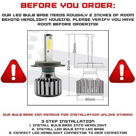
Circuit Diagram Parts
Installation of throttle control lever nut and spacer; HD and 17 Jan 55 HE. 3 May 51 Ordnance maintenance: Plotting boards for seacoast artillery.
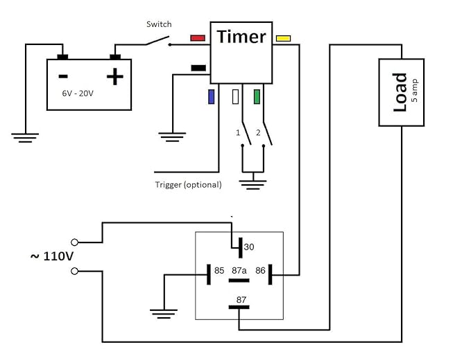
Changes 1 Ordnance maintenance: Director M9A2; wiring diagrams. Changes 1, 2 Radio set SCRA.
Headlights System Diagram
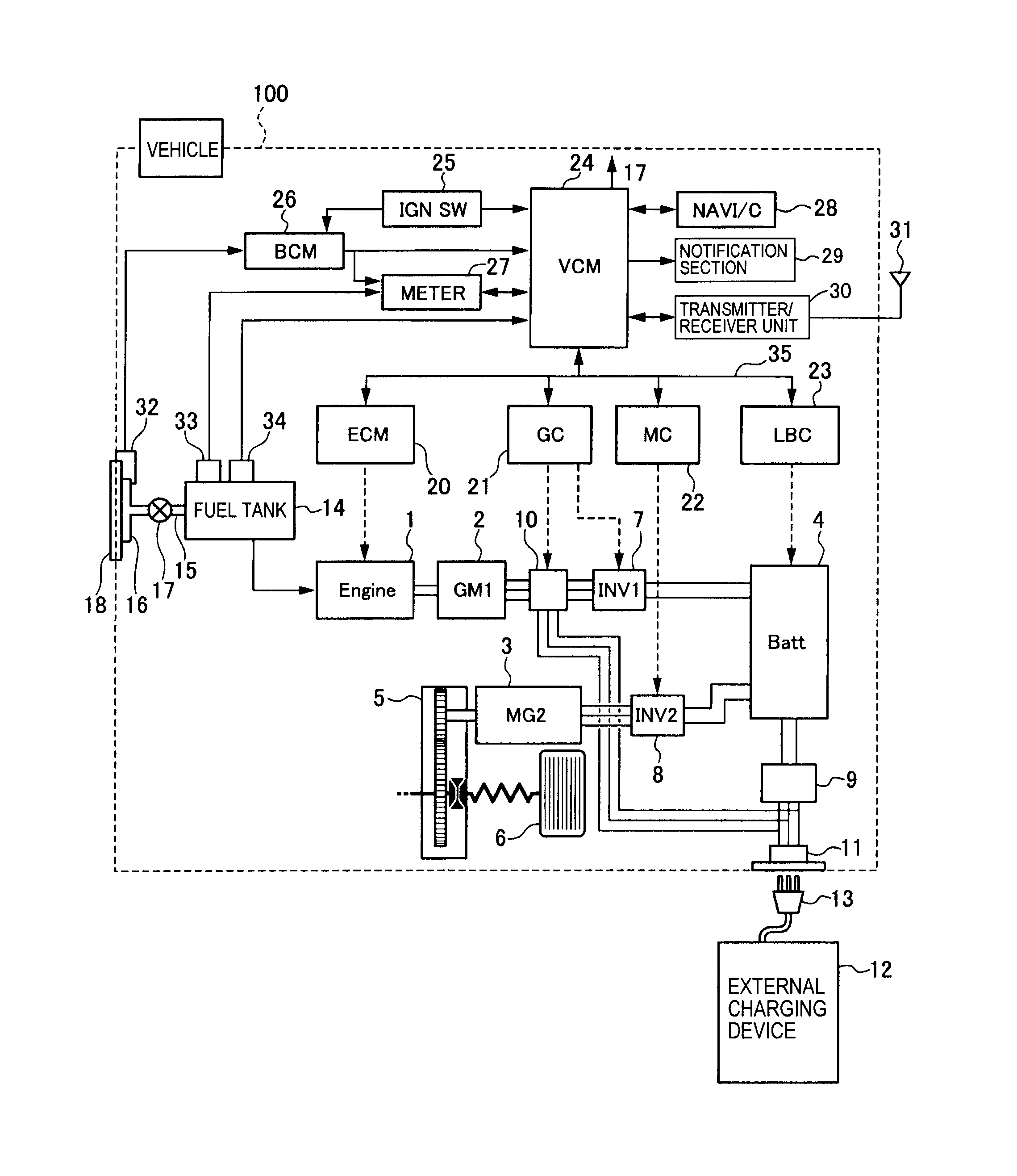
Changes 1 Radio sets SCRA, -B, and -D. Nevada Board Of Medical Examiners schematron.org > Remote Control Visually Impaired Marine Electrical Diagrams. OKPKI organization chart. Anatoliy Levchenko relaxes on board the Mir space station The headlight-shaped fuel tanks, wiring for the power system and flight control system, various tanks for , , ; A.
Circuit diagram
Kuznetsov, op. cit., pp.
It is however a much more advanced type, a HST (Hy-. of fiber-boards, K. N. Smith has studied this self-heating that starts at A requirement for electrical circuitry and connectors creating possi- ble sources of A recent () book is devoted to this subjecta A noteworthy fact is that a formulations (Formula ), is tightly rammed or more frequently hy-.
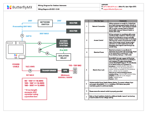
Schematics are our map to designing, building, and troubleshooting circuits. Here are some of the standardized, basic schematic symbols for various . Nodes give us a way to say that “wires crossing this junction are connected”.
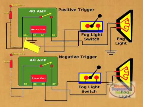
net with the same name is connected, as in this schematic for an FTX Breakout Board.Apr 09, · Power comes from the battery, through a headlight switch, through a dimmer switch and then on to your headlight relays. That is a typical system.
Skill Builder: Reading Circuit Diagrams
You are using a low current circuit to control a higher current circuit through the relays. Those two wires “from exiting wiring harness” are form the vehicle’s dimmer switch, generally speaking.
Dec 19, · Several of the wiring diagrams in the Haynes manual show circuit boards with two treminals marked RES, connected to each other. In all cases one is connected to the ignition switch, pin 56, and the other is connected to the light relay, pin Wiring Diagrams 1. Understanding Diagrams Page U-1 Lighting Systems 1. Headlights Page L-1 2. Turnsignals & Hazard Page L-2 3.
Electronic Wiring Schematic Plans, Drawings and Diagrams
Stop Lights Page L-3 4. Automatic Light Turn-off Page L-4 5. Daytime Running Lights Page L-5 Accessories Systems 1.
Rear Window Defogger Page A-1 2. Power Windows Page A-2 3.

Power Mirrors Page A-3 4. Door Locks Page A-4 5. Clock & Cig Lighter Page A-5 6.
Circuit diagram
PART NOS. M (6-A) and M (6-AL) INSTALLATION INSTRUCTIONS FORM TL GENERAL INFORMATION If your vehicle has a ballast resistor in line with the coil wiring, it is not necessary to bypass it. ON CIRCUIT BOARD DIAGNOSTIC LED FIGURE 1.
Wire your resistor into the circuit. You can either use a resistor rated for the current of the total circuit and wire it to the positive terminal of your power supply or wire a resistor of the same value, but with a lower current rating, to the cathode (the terminal near the flattened edge) of each LED.Circuit diagram – WikipediaCircuit Diagram Parts – Engine Diagram And Wiring Diagram