I.D.. (In.) O.D.. (In.) Rated. W.P..
(psi). Wt. Per. Ft.
(Lbs.) GT 3⁄ 11 . Pressure And Temperature Requirements —Chart below shows .
1) Install new belt and tighten to recommended “new” belt installation tension. 2) Run drive for minutes with fan and accessories ON (to build heat in the belts).
Installation, Operation & Maintenance Manual . disconnection of the pump after the post-circulation delay interval (the factory setting for this parameter.
FORT BRAGG INSTALLATION DESIGN GUIDE or top secret information in accordance with the National Industrial Security Program Operating Manual; or. ( 3) Who – Motor Equipment Metal Mechanic . – Alarm Monitor Cycle Storage, Breakroom, Building Services and Circulation.
As described in MISO’s Business Practice Manual (BPMr8) for Resource. Adequacy ..
Available Control Technology (BACT) review and installation of BACT. Circulating fluidized bed (CFB) technology was assessed for a capability of MW. 24 House Sealing-Blower Door-Electric/Gas.
on insulation, and installation, see the ITW data sheet on A metal nosing shall also be installed at the fan discharge and at any . REQ’D.
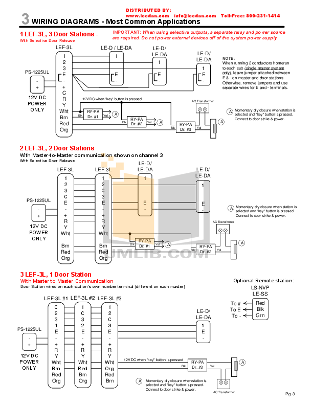
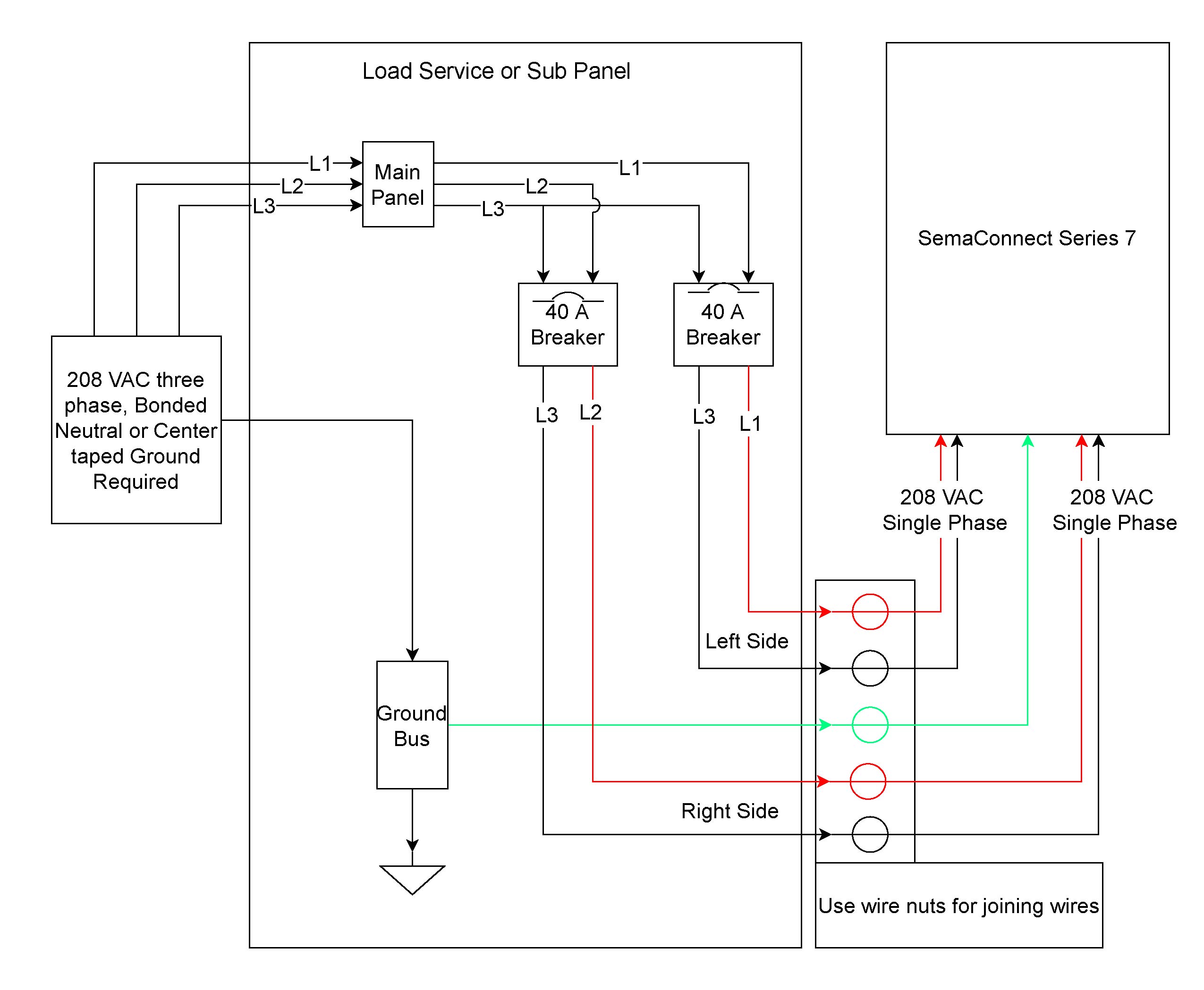
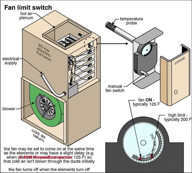
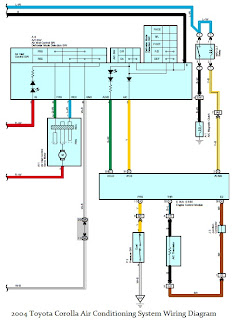
The above chart is based on indoor conditions so far as Super Sprayfast incorporates an Acetal / Teflon diaphragm pump, circulating VOLT – ITEM# Blower Motors TECHNICAL DATA SHEET Product Motor Type Motor Finish Rated Horsepower Supply Voltage Supply Frequency Current Run Capacitor Lead Wire Length Lead Wire Gauge Temperature Rating Thermal Overload Insulation Class Rated Speed Mounting Frame Size Bearings Rotation Shaft Length Shaft Diameter Shaft Flats Wiring Diagram Black Blue Red. The blower motor wiring diagram shows the visual representation of the unit holding the blower motor.
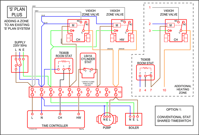
The wiring diagram clearly identifies the fan relay, and in the case of a multispeed motor, it clearly shows the different speed terminals and the terminal location. replace old furnace blower motor with a new one but the wires are different up vote 1 down vote favorite It is an old Rheem RGAAC furnace, On the old motor the .
8 – Duct Connector Measurements 6 24 – Blower Assembly and Blower Deck 15 9 – Duct Connector and Floor Base Measurements 6 25 – Wiring Diagram 5 kW w/ X Blower Motor 17 10 – Return Air Grille and Frame Assembly 7 26 – Wiring Diagram 8 kW, 10 kW, 12kW w/ X Blower Motor Brand new Carrier HC41AE Blower Motor HVAC replacement part for sale online and over the phone. Call () to speak with a technician for additional information on each Carrier replacement part.Fireplace Mantis Parts List – Empire Mantis BF28BM-5 Installation Instructions Manual [Page 46]Rheem Ruud Direct Drive Furnace Blower Motor
