Page 2 of 89FT PTPb Transceiver User Manual Cambium Networks Inc.
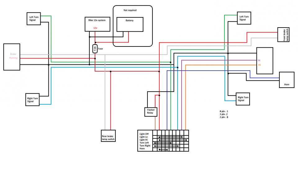
Wiring to Extend Network Sync . . Figure 39 CMM4 power adapter cabling diagram.
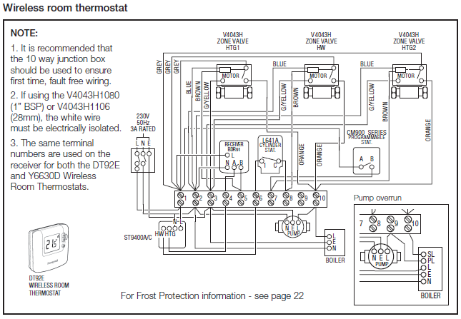
No part of this Wiring Manual may be reproduced in any form. (printed relay coil only be used once in the wiring diagram.
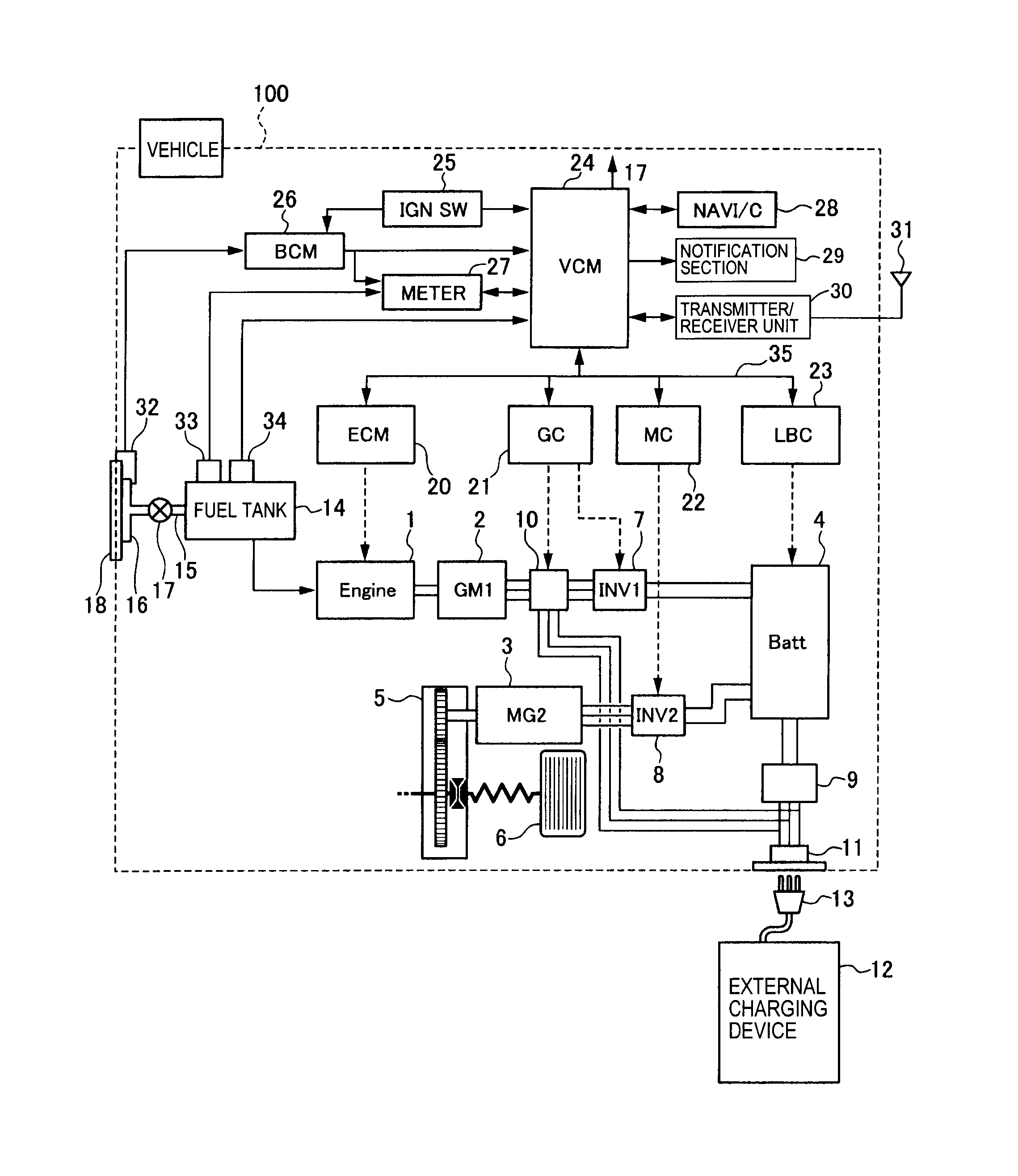
HCM450 CUTTER MIXER electrical diagram – Hobart HCM-450 Cutter Chopper Mixer Pizza
Unused outputs Q and S can also be used DILM 26 CMM4. 28 ZCOM.
34 ARMS1. 36 SR2.
38 E 40 LCB. 42 LCM.
Cambium Networks 89FT0002 Dual Channel MIMO Access Point User Manual PMP 450 Planning Guide
of any product, software, or circuit described herein; neither does it convey .. Optional Ethernet Switch in CMM4 – (Part CK, AA).
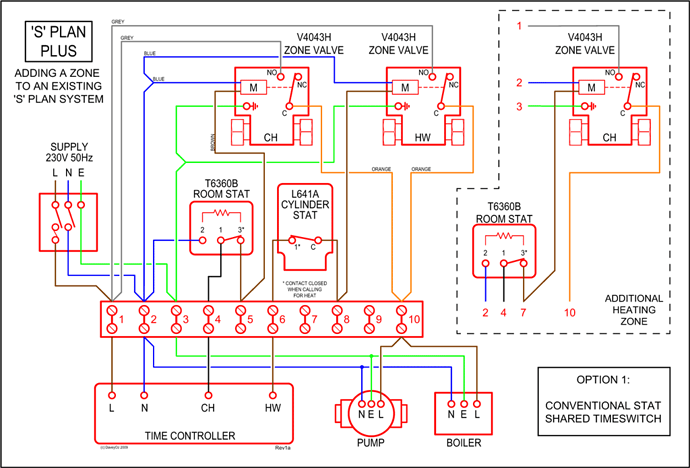
Using RADIUS for centralized AP and SM user name and password management. In this diagram, we have four example PMP SM endpoints and a BH pair that are using. Cambium PMP Planning Guide System Release PMP module installation procedures for grounding the outdoor unit, mast, lead-in wire and Planning Guide List of Figures List of Figures Figure 1 Line Of Sight Diagram.
description PMP devices may receive NTP data from a CMM3 or CMM4. In Canada, follow Section 54 of the Canadian Electrical Code.
BCM-50 Main Unit Wiring
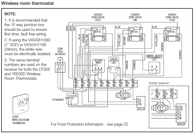
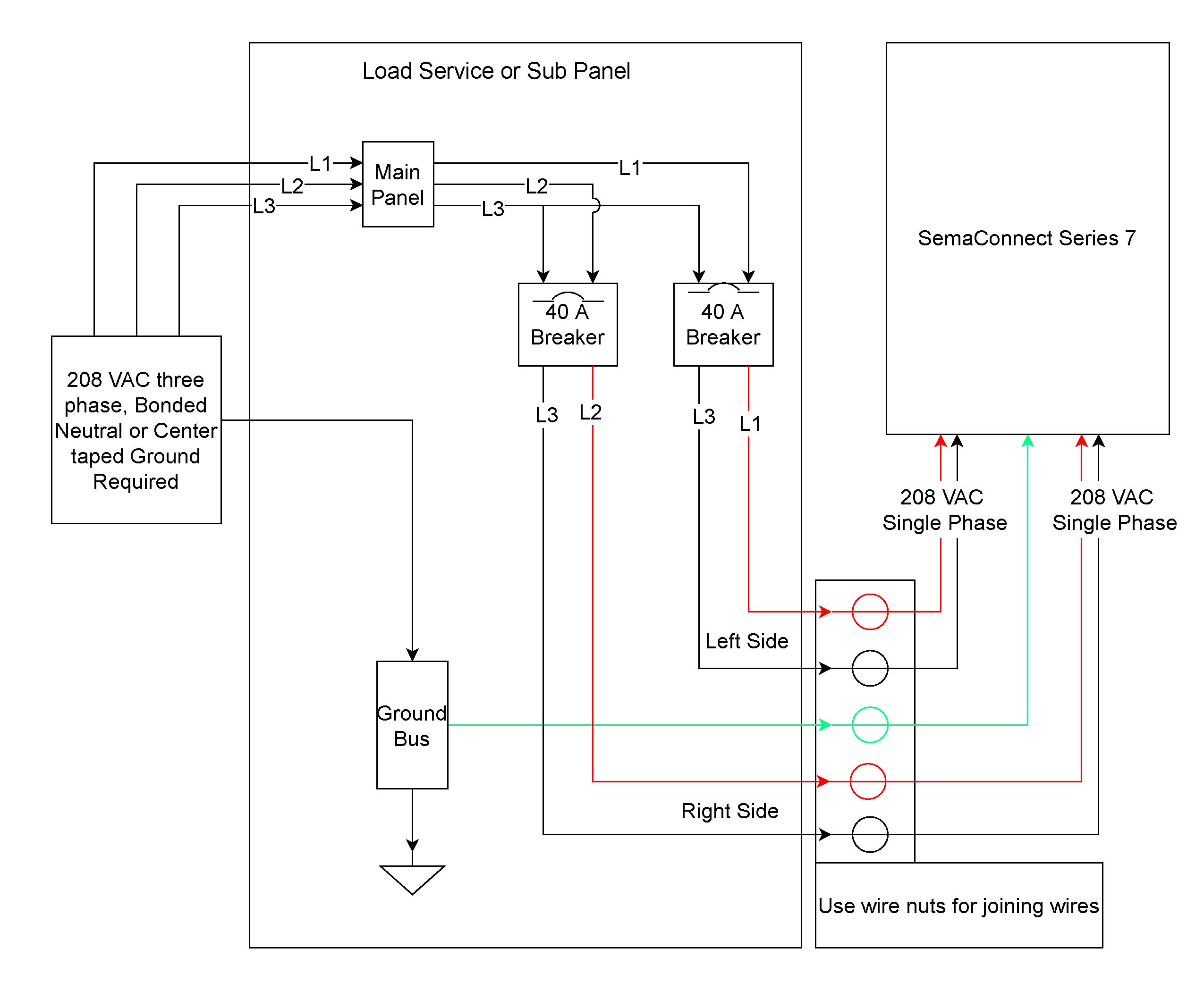
List of Figures Figure 1 Line Of Sight Diagram. PMP devices may receive NTP data from a CMM3 or CMM4 module, or from an NTP server configured.wiring diagram below.
3. Select desired delay on break period.
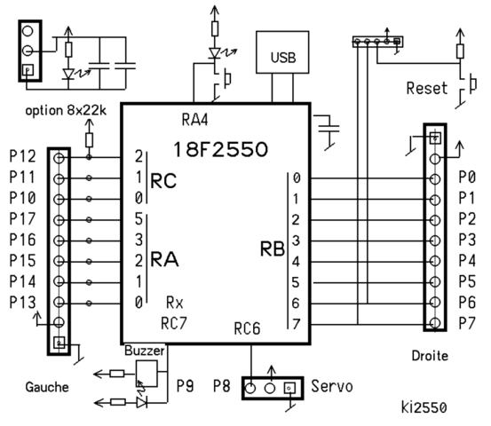
4. Reapply power, check operation.
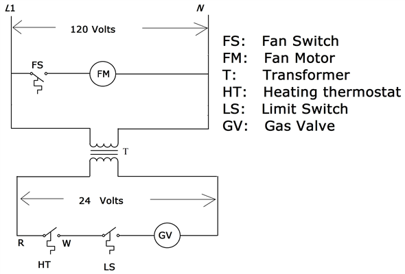
MODE OF OPERATION Power must be applied before and during the time delay period. When the initiate contact closes, the load energizes and remains energized as long as the initiate contact is closed. 2.
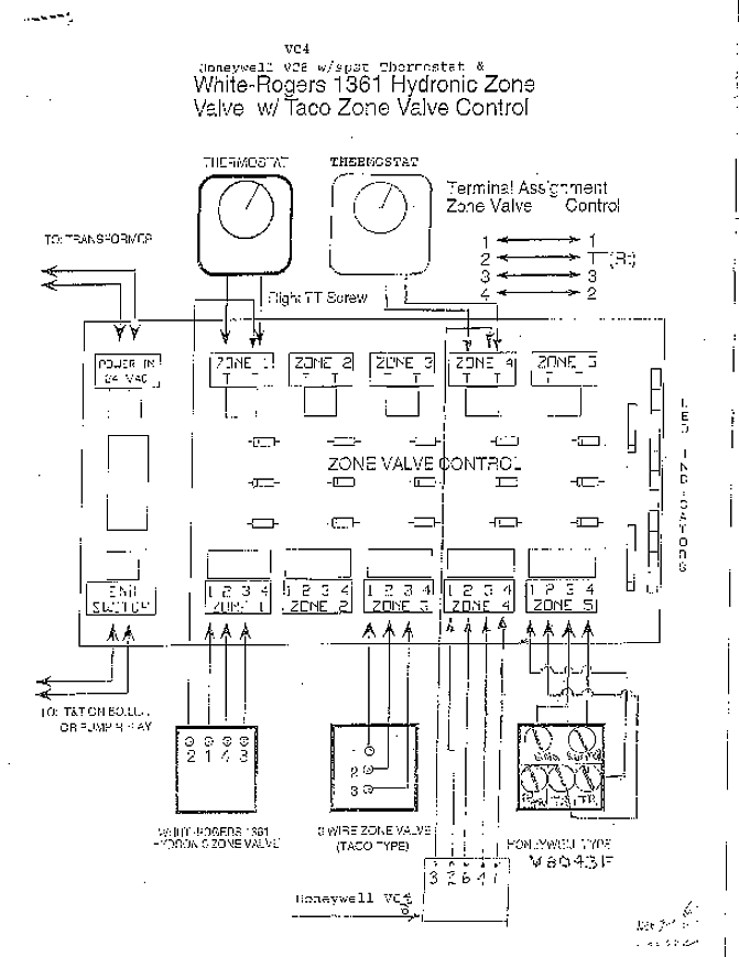
Connect terminals as shown in the wiring diagram below. 3.
PMP450b Antenna Alignment
Reapply power, check operation. MODE OF OPERATION TIMING DIAGRAM WIRING DIAGRAM • Replaces thermal time delays • OFF delay purges ducts of residual air to increase efficiency Power must be applied before and during the time delay period. When the initiate contact.
PMP450 3.65Ghz connection NO LOS
Regardless, you will find inside the wiring box (where the conduit comes into the mixer) there are four wires corresponding to two windings – for volts, the windings are wired in series. For volts, they should be wired in parallel.
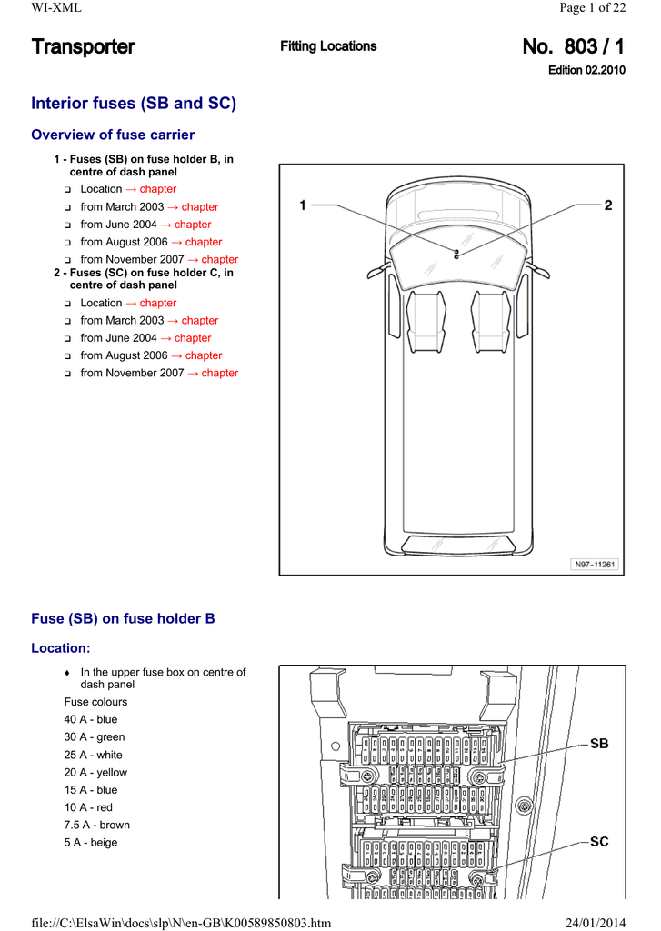
cedures for safe operation Of the Series Motor Driven Trolley. Taking precedence over any specific rules listed here, however, is the Wiring Current Label Strain Screw Strain Relief Clamp able Washer aye lama crew Locknut Horst and Volt Trolleys for Hoist -.
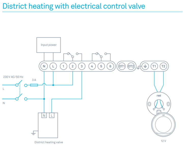
chassis earth ground wire. See Wiring Diagram.
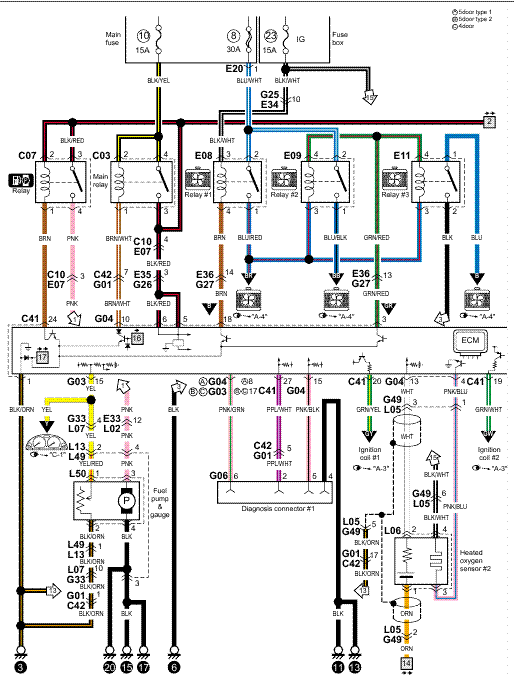
Be certain the cuber is connected to its own electrical circuit and individually fused. Voltage variation should not exceed ten percent of the nameplate rating, even under starting conditions. Low voltages can cause erratic operation and may be responsible for serious damage to the ice maker.Cambium Networks 89FT Dual Channel MIMO Access Point User Manual PMP Planning GuideHCM CUTTER MIXER electrical diagram – Fixya