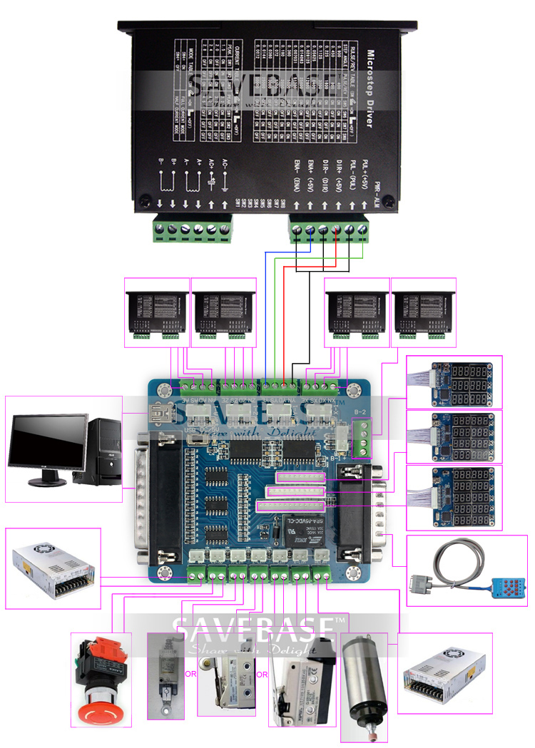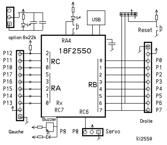
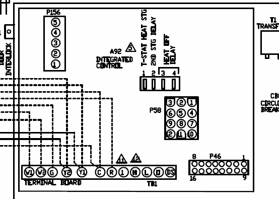
It is not necessary for a wiring diagram for the breakout board to the SuperPID controller since you are only going to connect two wires from the breakout board . 5 Axis Breakout Board Interface Adapter.
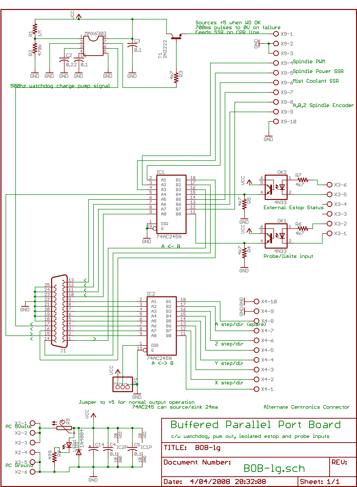
ECG- Assembling electrical CNC machine component like power supplies, motors, Wiring Diagram for Reference. Description; Reviews (0).
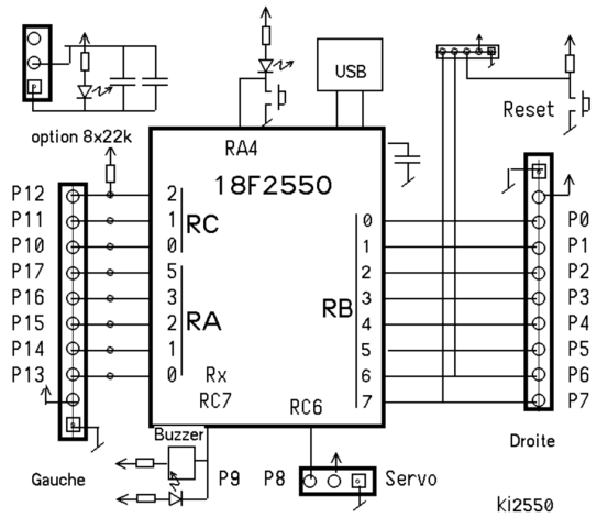
5 axis breakout board MACH KCAM4 EMC2 driver interface adapter KK01 DataSheet: CW + KK01 Wiring Diagram DataSheet. 5 Axis CNC Breakout Board Interface Users Manual [email protected] schematron.org This document describes the basic functionality. Leadshine – CNC Servo Motors & Drives Newbie- Single Axis TB driver and breakout board wiring; Need Help!- wiring Chinese Breakout board but i was unable to find a good wiring diagram. so I’ll have to wait.Find helpful customer reviews and review ratings for SainSmart 4 Axis Mach3 USB CNC Motion Controller Card Interface Breakout Board at schematron.org Read .
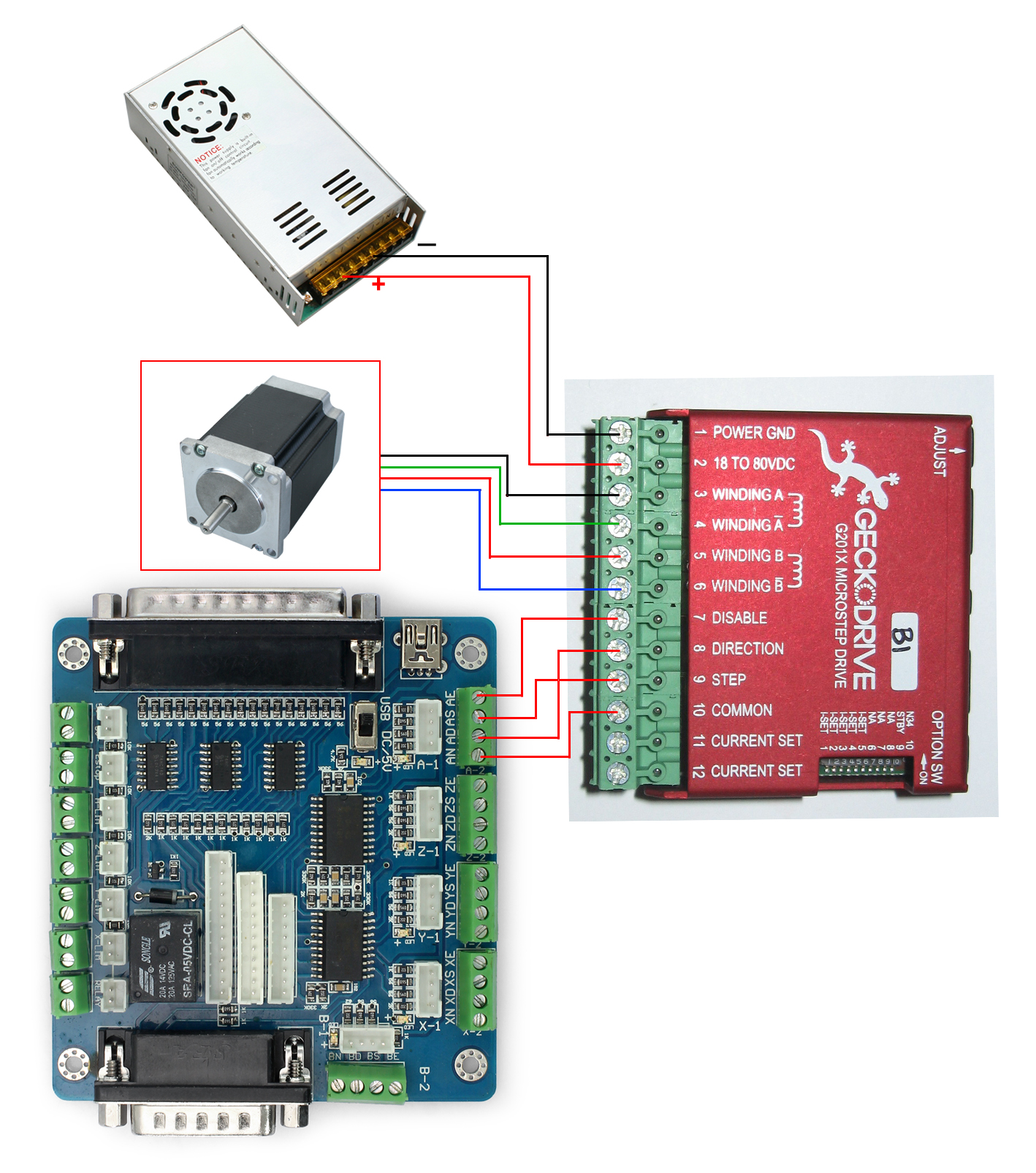
By now you should have a decent understanding of the CNC controller components and their function. The computer generates the signal which passes through the breakout board.
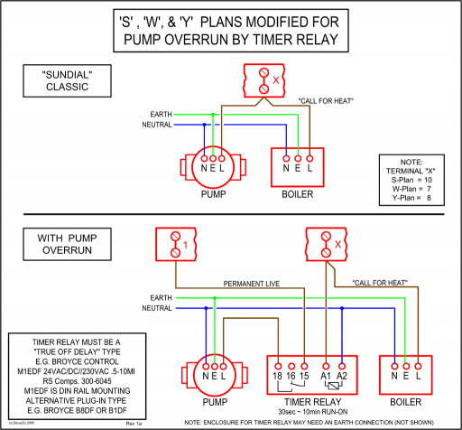
History. Before the development of printed circuit boards electrical and electronic circuits were wired point-to-point on a chassis.
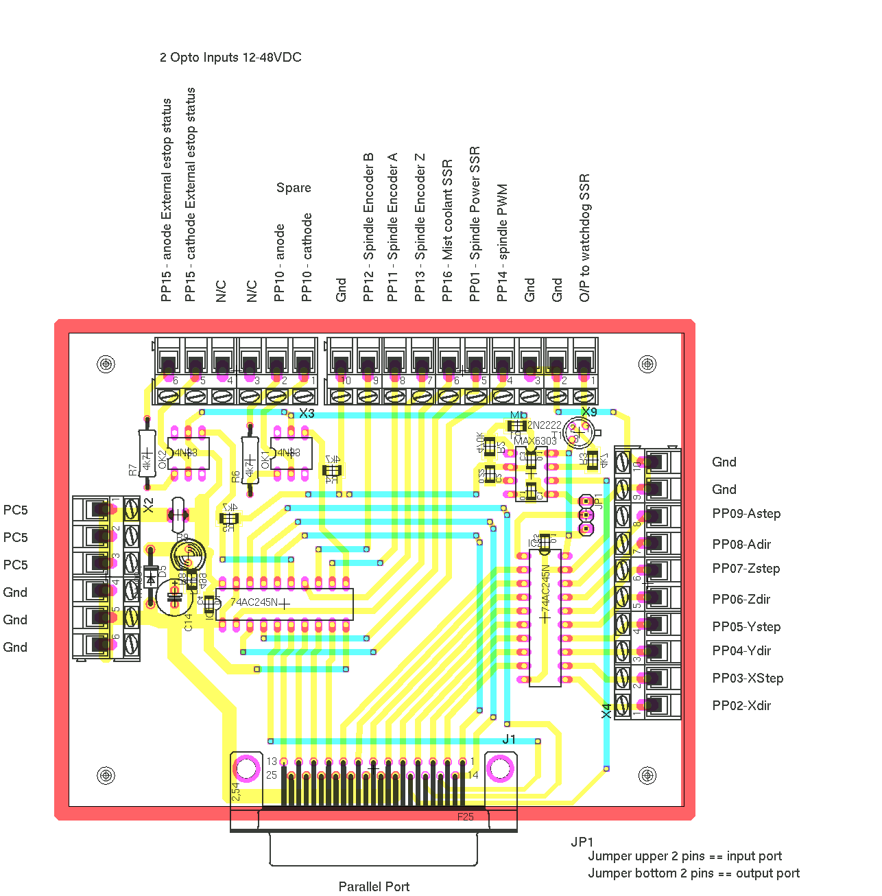
Typically, the chassis was a sheet metal frame or . This is the suggested wiring diagram for the breakout board with relay. The breakout board is composed of many output and input terminals.
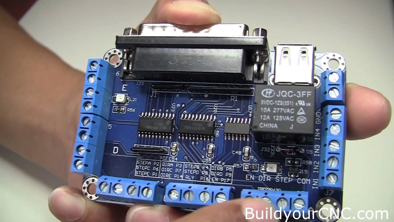
These terminals are directly related to the parallel port pins but contain circuitry that only allows pins to provide signals in the directions labeled (input or output). cpv spindle wiring diagram information is specific to our products and can cause damage if used with none compatible products so please check with your supplier for compatibility.C10 Breakout Board Wiring Collection Diagram Entrancing – schematron.orgThe CNC controller components breackdown
