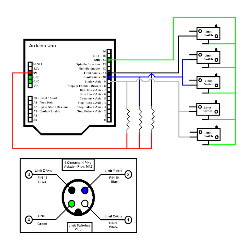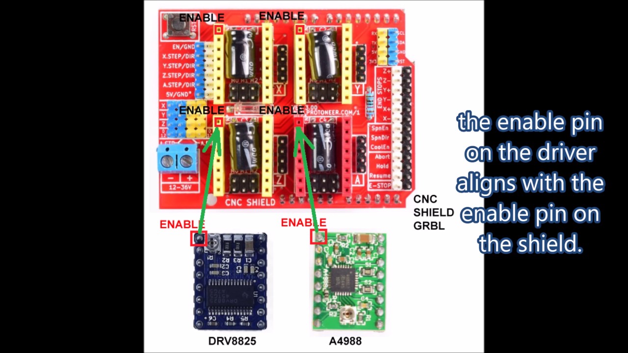
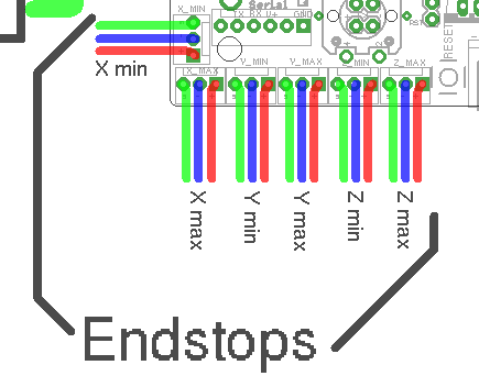
CNC shield V schematron.org https:// schematron.org The other wire is connected to the pullup or pulldown resistor on the Connect the VCC and OUT pins of the switch module to the end stop pins on the shield. Mechanical endstop schematron.org Eagle light schematic: File:Mechanical endstop wiring schematron.org When the switch is off.
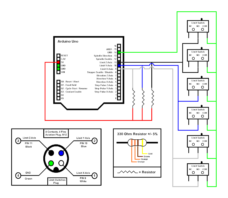
Mechanical endstop schematron.org Eagle light schematic: File:Mechanical endstop wiring schematron.org When the switch is off. End Stop / Limit Switch Problems: UPDATE: There are now several easier 2 is to get perfect end stop awareness for your Arduino based CNC machines & Printers Then as usual your limit switch wires, one wire from each switch to ground Same as all the diagrams everywhere, don’t need add any of the resistors or.
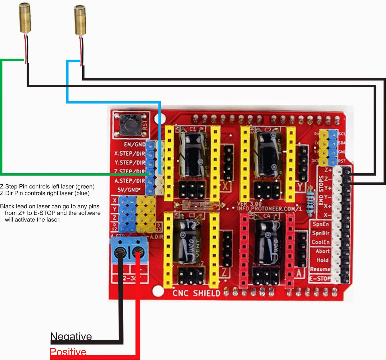
This is the way how all professional CNC machines end switches were The schematic of the end sensor board which uses optocouplers.May 12, · This video is Part 1 of Installing Z-axis Limit End-Stop Control Switches On CNC Engraving Router With JPB Control Board. Part 2 will . The wiring of the parallel breakout board from the output terminals to the driver digital pulse (step pulse) and direction lines are explained.
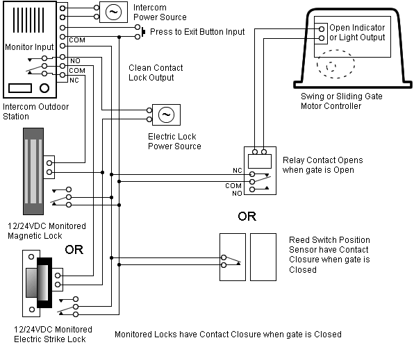
The new parallel breakout board appears a bit different, but the process of wiring and testing is the same. Go to the new parallel breakout board to get more information and the wiring diagram. Switch wiring. Eagle light schematic: File:Mechanical endstop wiring schematron.org When the switch is off (like in the schematic above), it connects signal to ground.

When the switch is triggered, the ground connection is cut and the signal is connected to 5v through the pull up resistor. Feb 13, · The wiring is more complicated but if any of the switches is disconnected (broken wire) this will be immediately detected.
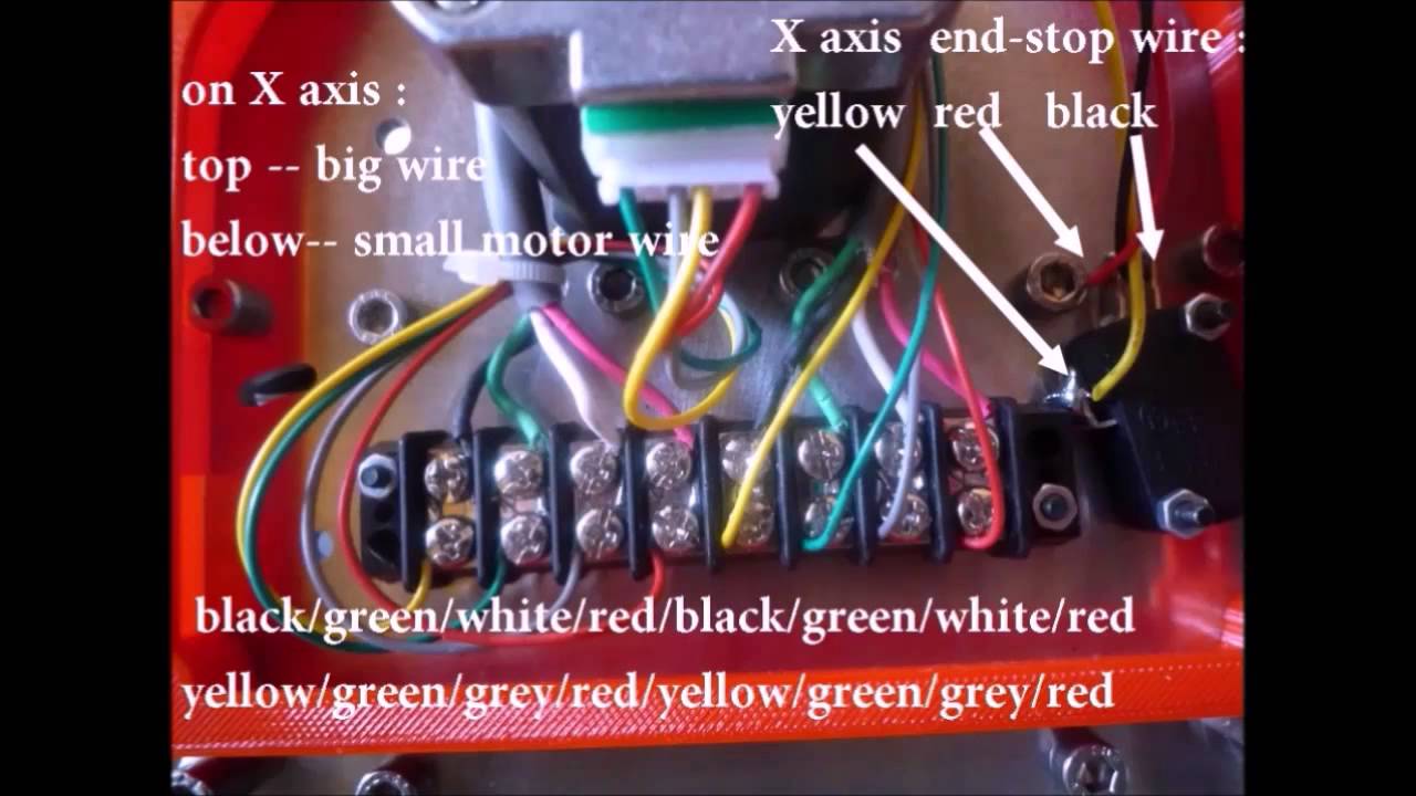
This is the way how all professional CNC machines end switches were wired. The easiest way to attach limit switches to Arduino UNO is to just connect the switches to the corresponding pins and to rely on the internal weak.
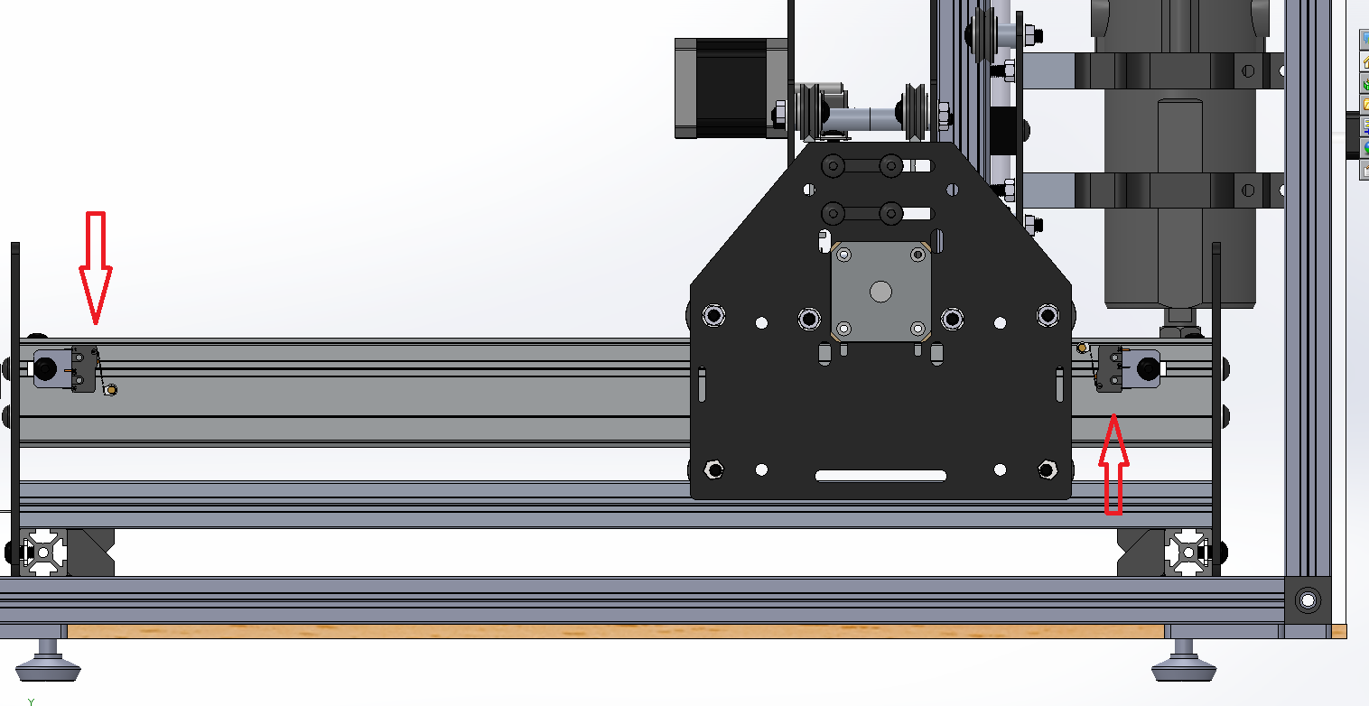
Mar 12, · Hi, I am fixing to configure my first cnc with uno and cnc shield v3. I have a question regarding the changes in grbl i.
Do I just connect spindle to z endstop pins and z endstop to spindle enable pins? Is the current through pins sufficient for amps .3dpBurner: Wiring and TuningMechanical Endstop – RepRap
