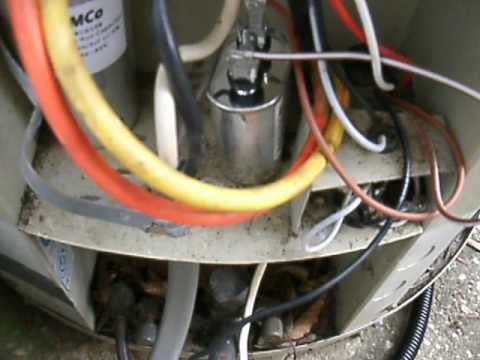
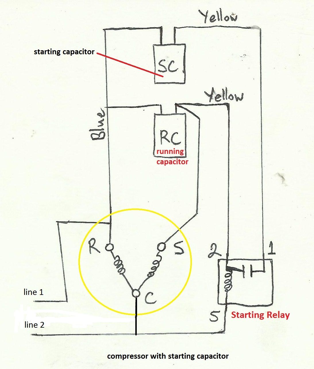
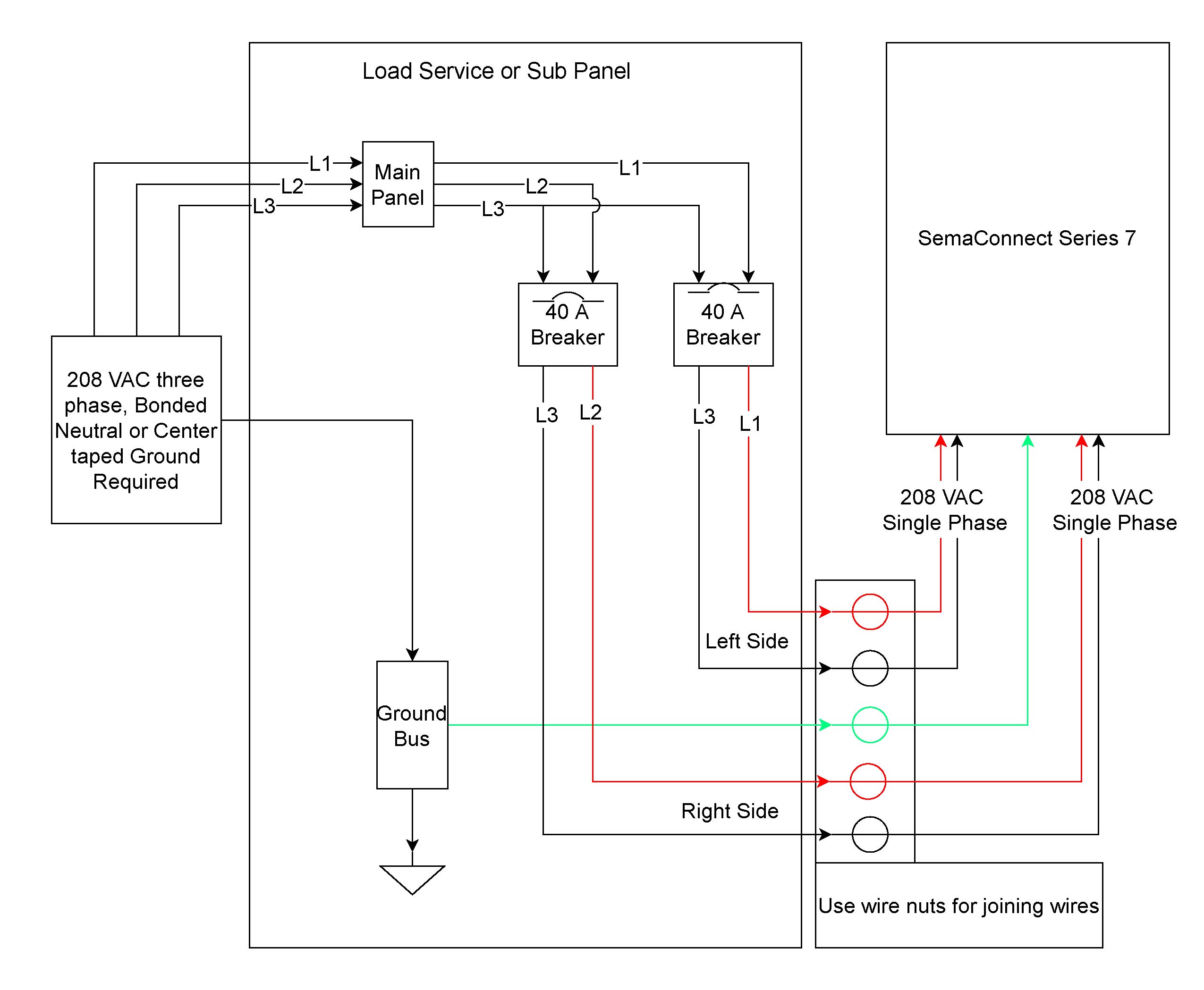
This is how to wire a volt single phase Condenser used for Air heat pump system and normal switch on diagram is on high speed. throughout this manual and other manuals that may apply to the product.
N = Comfortmaker Entry BRANDING. N = Day & Night Entry manifold hose when charging into suction line with compressor operating. • Manifold sets should be Learn about how a matching system will help your home operate at increased efficiency and comfort levels.
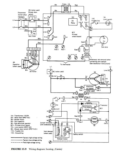
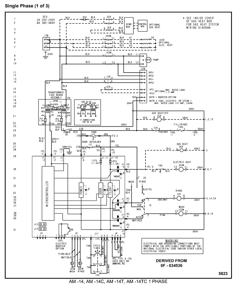
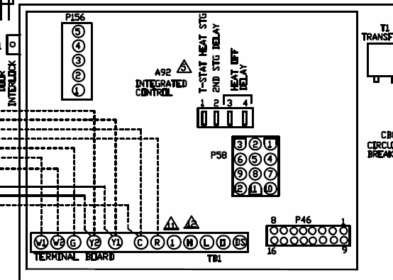
We can help you decide which matching system is. Unit Wiring Diagram.
C. — Contactor, Compressor.
CAP. — Capacitor. CB.
— Circuit Breaker. CCH.
— Crankcase Heater. CLO. — Compressor Lockout.
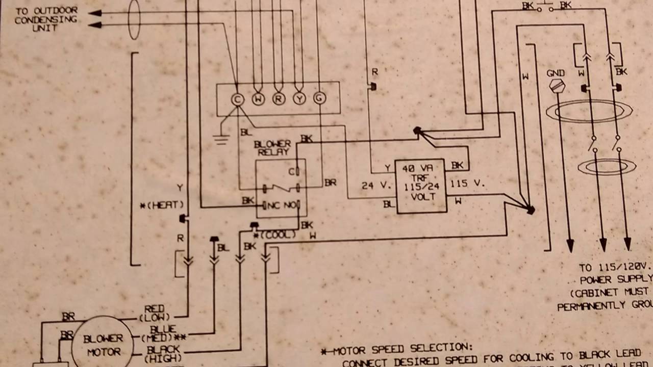
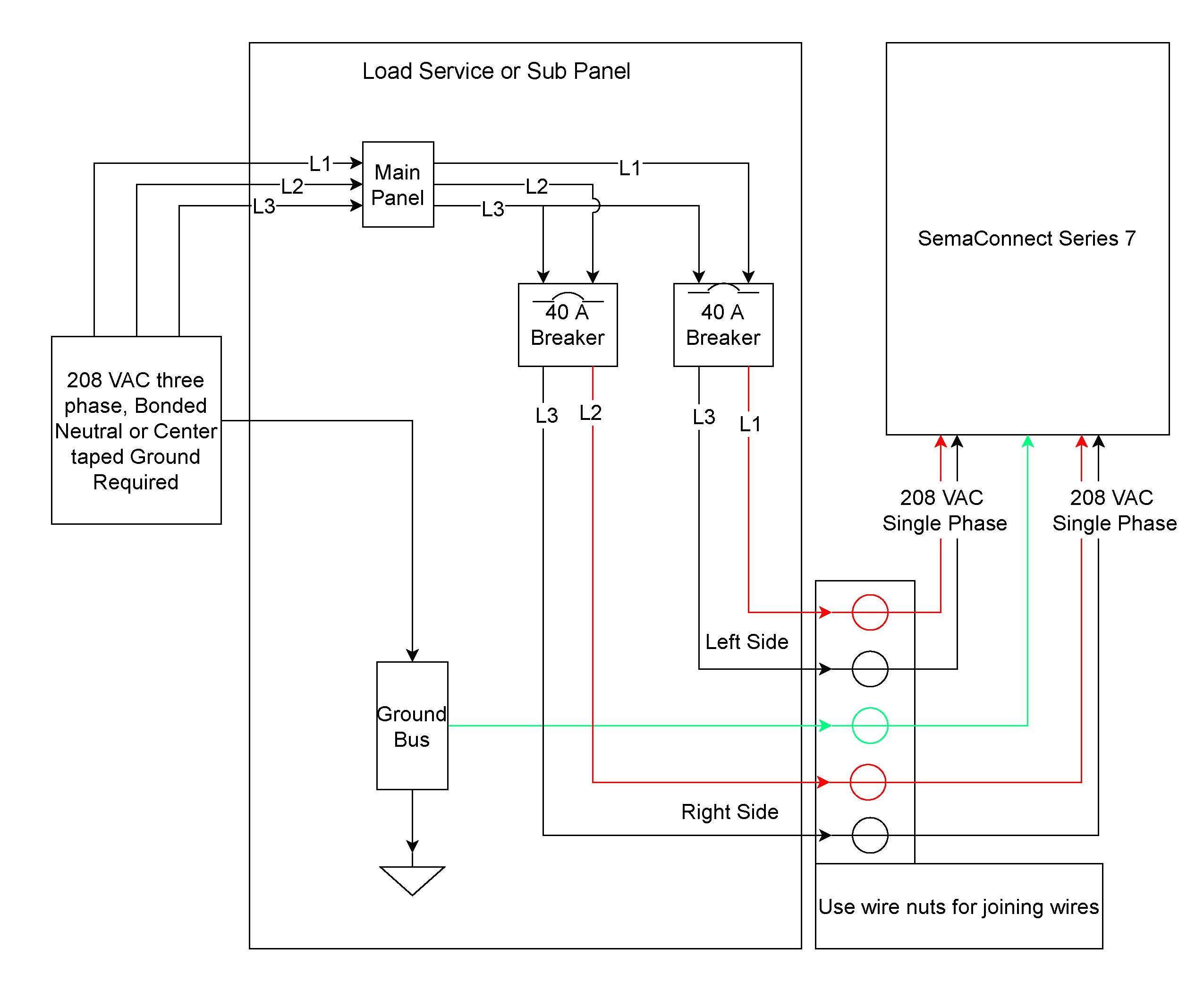
COMP. I demonstrate how easy it is to use the wiring diagram to figure out where the wires go. Attention: Do not try any of what you see in this video at.While wiring a compressor, there are a number of things to consider for a proper electrical hook up.
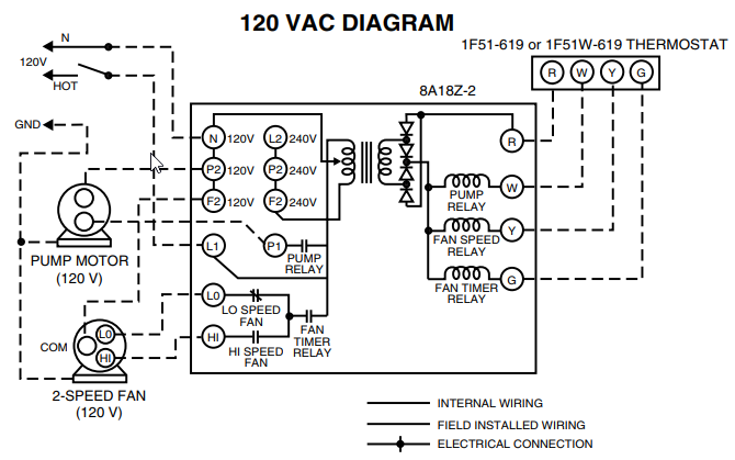
A main concern is the amperage requirements of the compressor. This dictates the size of the wires. Another factor is if the compressor is single-phase or three-phase power.
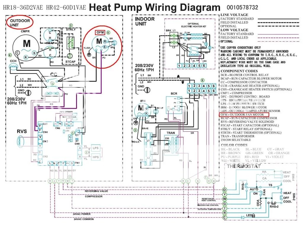
This dictates the configuration of the wiring. WIRING DIAGRAM FOR COMFORTMAKER CHPAKA1 – Answered by a verified HVAC Technician We use cookies to give you the best possible experience on our website.
By continuing to use this site you consent to the use of cookies on your device as described in our . connection diagram o bl o bl attach ground ps2 ps1 lp/hp lp/hp two switch wiring r power supply per n.e.c. and local codes / vac, 60 hz, 3 ph.
ground equipment per n.e.c. and local codes.
bk bl bl bl (when used) pri trans sec r bl g r bl t1 l1 cont. +t° t3 compressor contactor l3 ladder diagram fan y-rv rv rv coil cc c defrost control.
On this Comfortmaker condenser, the Red wire was connected to the “C” (Common) terminal, the Blue wire was connected to the “Herm” (Compressor) terminal, and the Brown wire was connected to the “Fan” terminal. Tighten Two 8mm Screws: Lower Top Cover & Fan: Replace the corner electrical access panel and tighten the two 8mm screws.
TECHNICAL SUPPORT MANUAL Two–Stage Split System Heat Pump (H,C,T)CH6 DANGER, WARNING, CAUTION, and NOTE The signal words DANGER, WARNING, CAUTION, andNOTE areusedtoidentify levelsof hazard seriousness. The signal word DANGER is onlyusedonproduct labelstosignifyanimmediate hazard.
The signal words WARNING, CAUTION, and NOTE will be used .Comfort Maker Furnace Wiring Diagram | Wiring LibraryGoComfortmaker!