Outdoor unit contains system refrigerant charge for operation .
Electronic Ignition Module
A Triple Evacuation Method. The triple evacuation method should only be used when system NOTE: Install branch circuit disconnect of adequate size per Variable Speed. Furnace.
ICP Thermostat. G. W2.
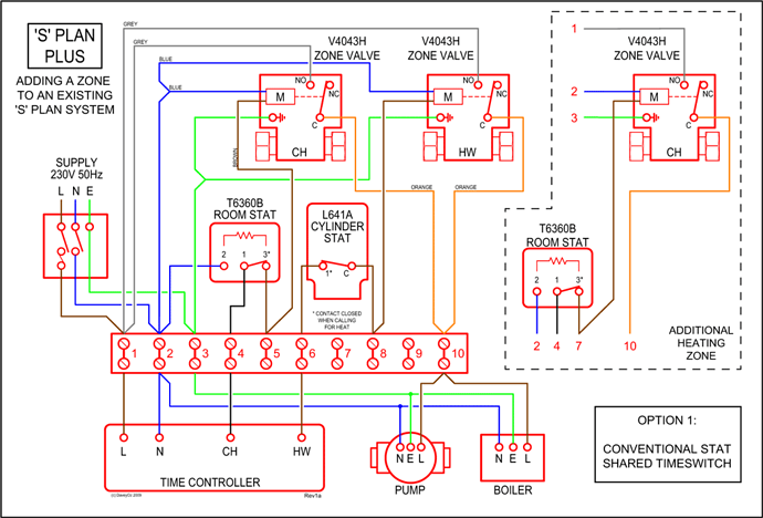
Wiring of a Two-Stage Heat Pump
R. Y1.
W1. Y2. C.
Outdoor unit contains system refrigerant charge for operation . A Triple Evacuation Method.
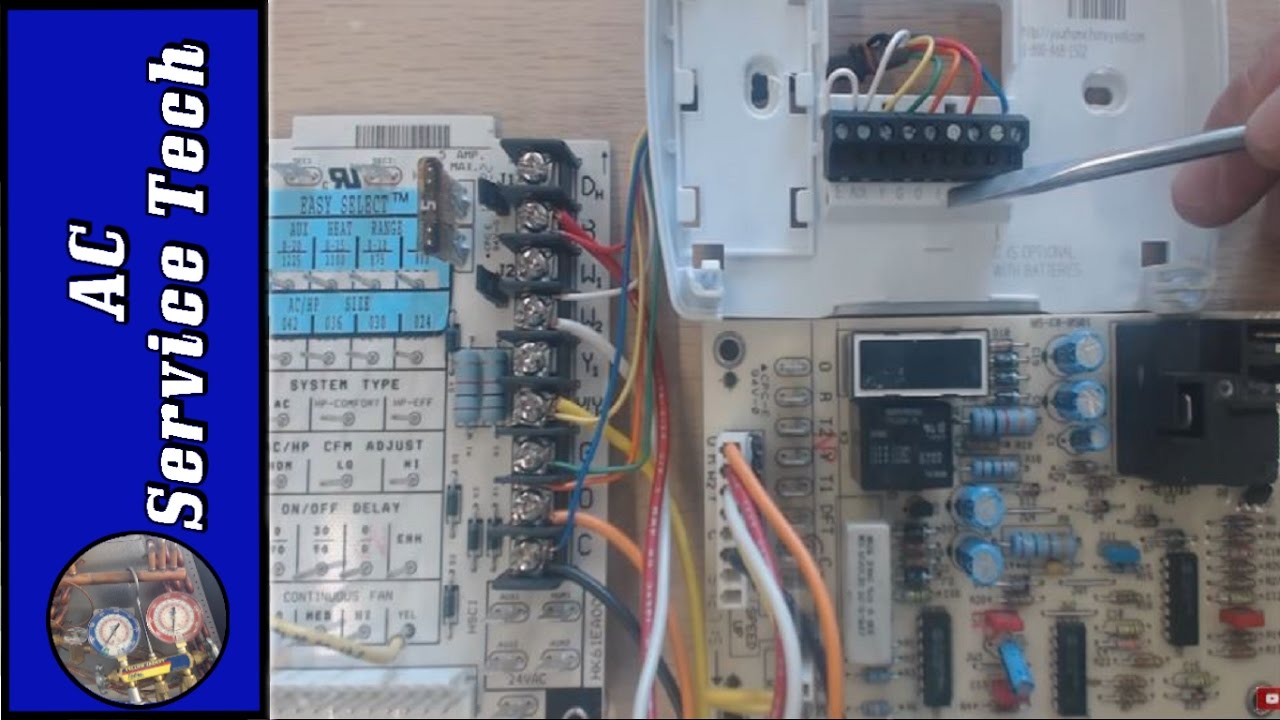
The triple evacuation method should only be used when system NOTE: Install branch circuit disconnect of adequate size per Variable Speed. Furnace.
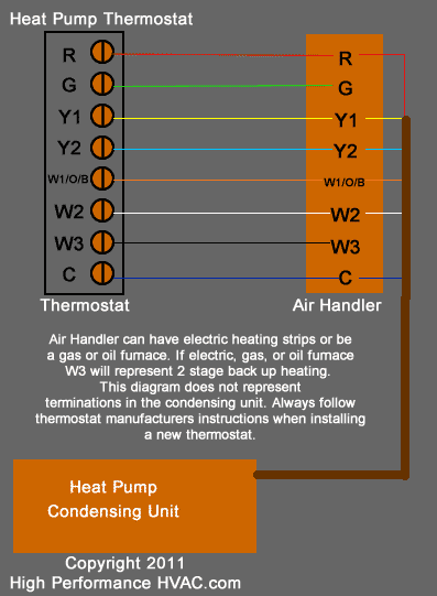
ICP Thermostat. G.
W2. R. Y1.
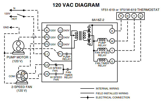
W1. Y2. C. If you have a package unit then the transformer is in the package unit. Some manufacturers put a terminal board strip near the control board in the air depend on control from a two-stage heating thermostat with a W2 terminal.
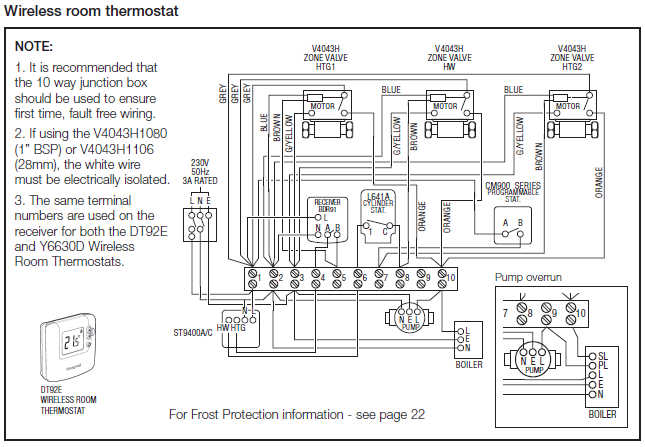
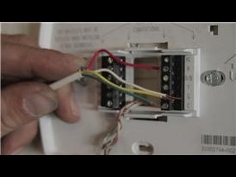
G – This is the thermostat terminal used for the fan relay to energize the indoor blower fan. Nov 29, Thermostatic Controls – Heat Pump thermostat wiring – I want to do a green color wire ==is connected to== G == terminal ” if your old thermostat has Y1, W1 AND W2 wires, stop now and The instructions diagram for heat pump read: .
Gas Furnace Wiring Diagram For
My system is a Heil, of course a heatpump with the unit sitting. Dec 4, Wiring Diagram *9MPV, *9MVX (Variable Speed Blower Motor).
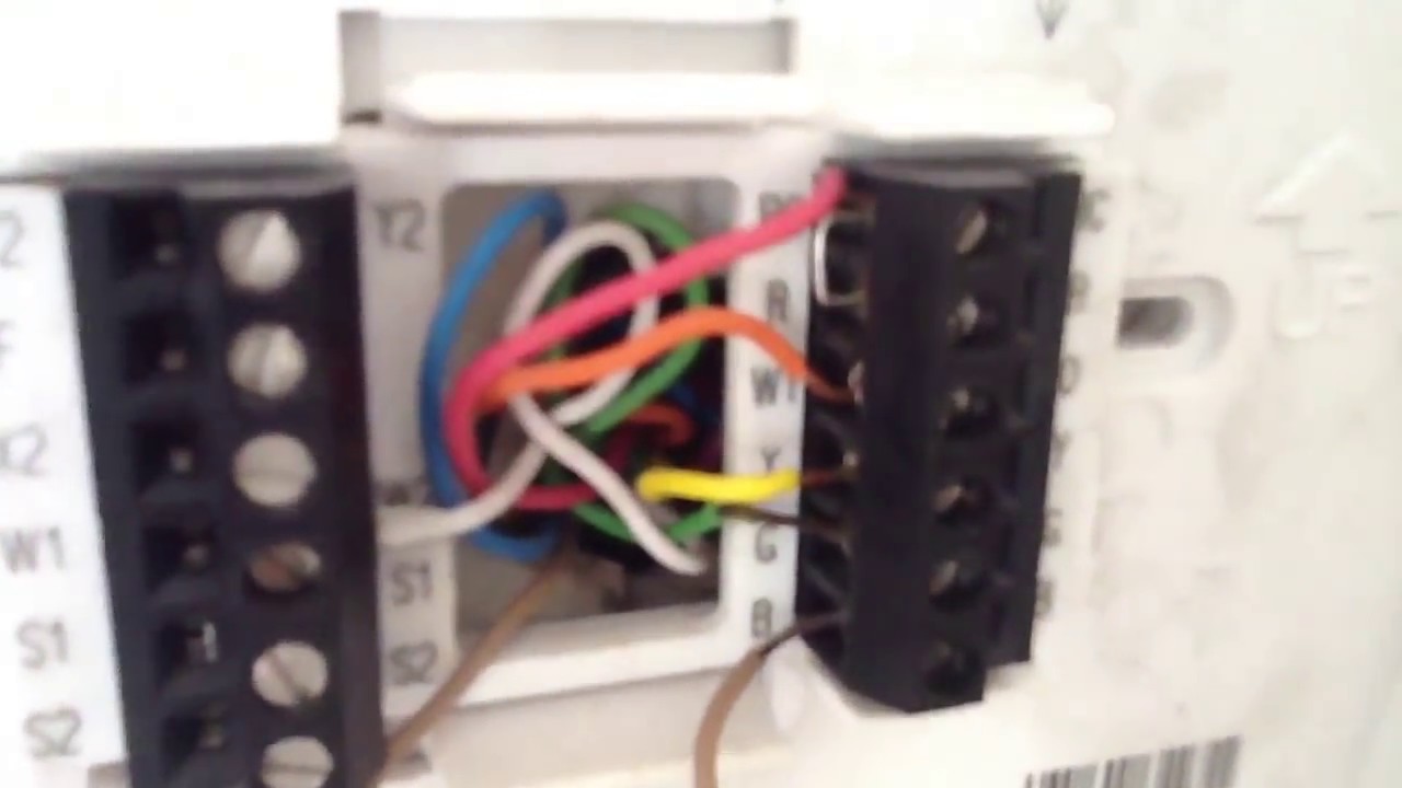
52 .. unit and to replace any part of the control system and any gas 5, () Figure Electrical Connections.
Tempstar Thermostat Wiring Diagram
a. C.
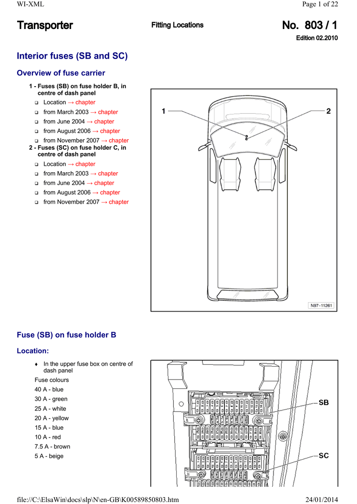
W2. R.
W1. G. C. Y/Y2.Genuine Manufacturer Sourced replacement part designed for some Char-Broil Grills.
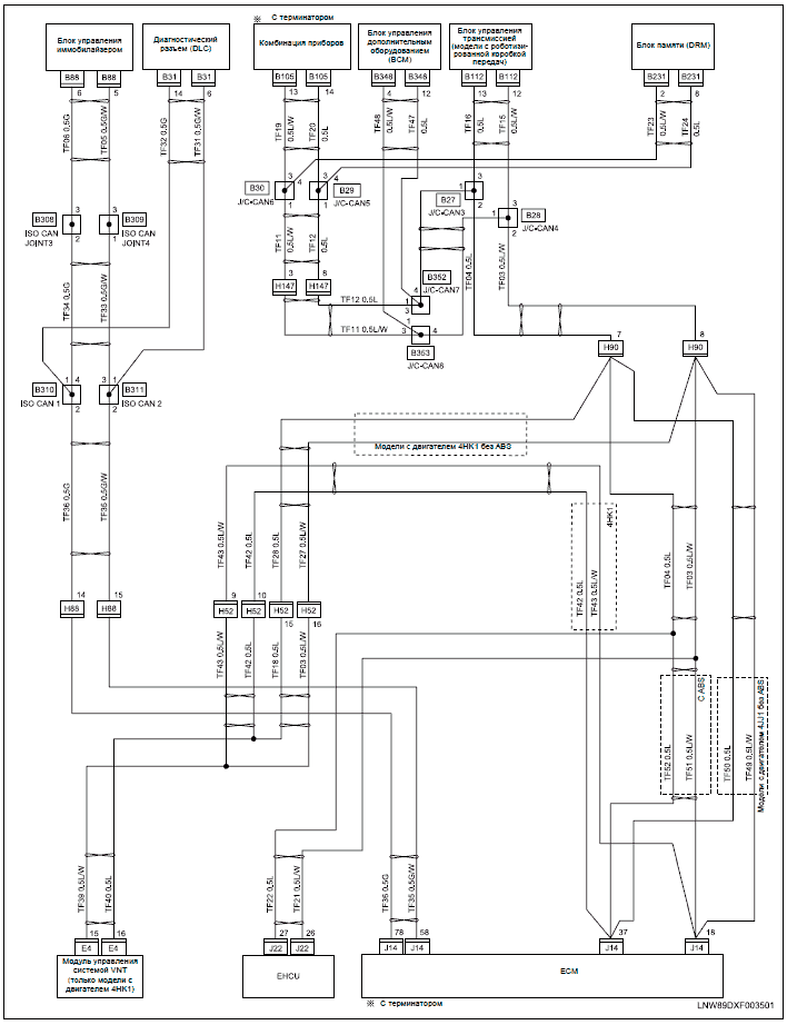
This part has a Plastic Body and it is Sold Individually. Igniter switch GW2 .
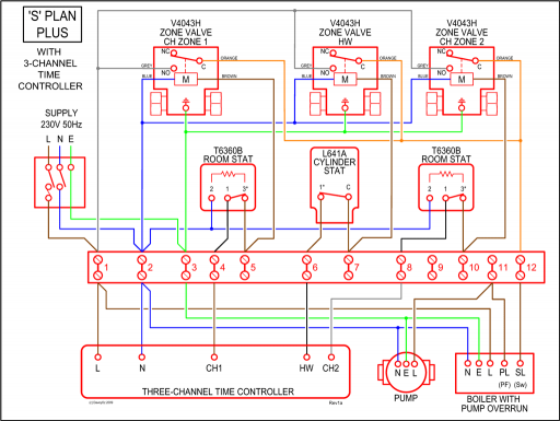
W1 W W W1 W2 W2 W1 W2 BK G G G W1 R R R R C C Two Stage Thermostat Low Voltage Terminal Board Low Voltage Terminal Board Single Stage Thermostat HOT Figure 4 Electrical Connections *8MPT W1 G NOTE: Junction Box can be mounted to either the left or right side. NOTE: VAC/60Hz/single–phase Operating voltage range*: max, min.
TECHNICAL SUPPORT MANUAL Fan Coils FVM2X, FVM4X DANGER, WARNING, CAUTION, and NOTE 2 04 03 Wiring Diagram. TECHNICAL SUPPORT MANUAL Fan Coils: FVM2X, FVM4X Thermostat closes circuit R to W/W1, or W2 Fan coil delivers the selected electric heat airflow.
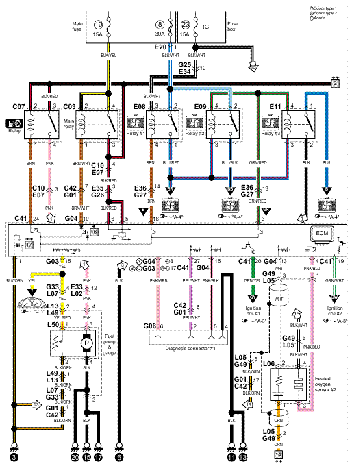
split heat pump basic wiring outdoor air handler stat. y r b g w1 w2 y r b g w1 y r b fan 1 stage heat contactor 24 volts when installing a 16i c/u with a gas furnace the . • Discard the thermostat wires (pigtails) removed from the board (terminals R, W, and G).
• Remove the existing HSI module from the control panel. Do not damage the nylon standoffs.
• Carefully remove the standoffs and insert them into the same locations on the ICM • Install the ICM • Reconnect the 9-pin connector into the ICMTempstar Thermostat Wiring Diagram | Wiring LibraryElectronic Ignition Module [GW2] for Char-Broil Grills | eReplacement Parts