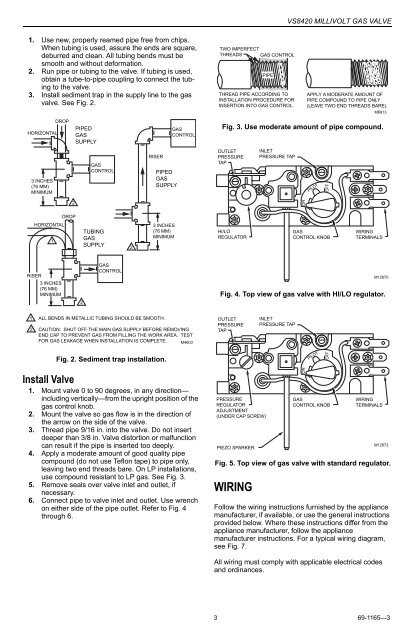
Control valves play a crucial role in various industrial processes by regulating the flow of fluids or gases. They are an essential component of any system that requires precise control over the operation of valves, such as in HVAC systems, chemical plants, and power generation facilities. The wiring diagram of a control valve provides valuable insights into how the valve is wired, which helps technicians and engineers understand its electrical connections and troubleshoot any issues that may arise.
A control valve wiring diagram typically includes information about the power supply, control signals, and various electrical components associated with the valve. It helps visualize the wiring layout and the interconnections between different parts of the system. This diagram acts as a guide for technicians during installation, maintenance, and troubleshooting activities.
In a control valve wiring diagram, the power supply source is usually indicated, along with the voltage and current ratings. The diagram also specifies the type of control signals, such as analog, digital, or pneumatic, that are used to operate the valve. Additionally, it shows the wiring connections to and from the valve, including any control panels, relays, or switches that are involved.
By referring to a control valve wiring diagram, technicians can identify potential wiring errors, faulty connections, or component failures. This allows for timely repairs and ensures the proper functioning of the control valve and the overall system. Understanding the wiring diagram is crucial for maintaining the safety, efficiency, and reliability of industrial processes that rely on control valves for precise flow control.
Understanding Control Valve Wiring Diagrams
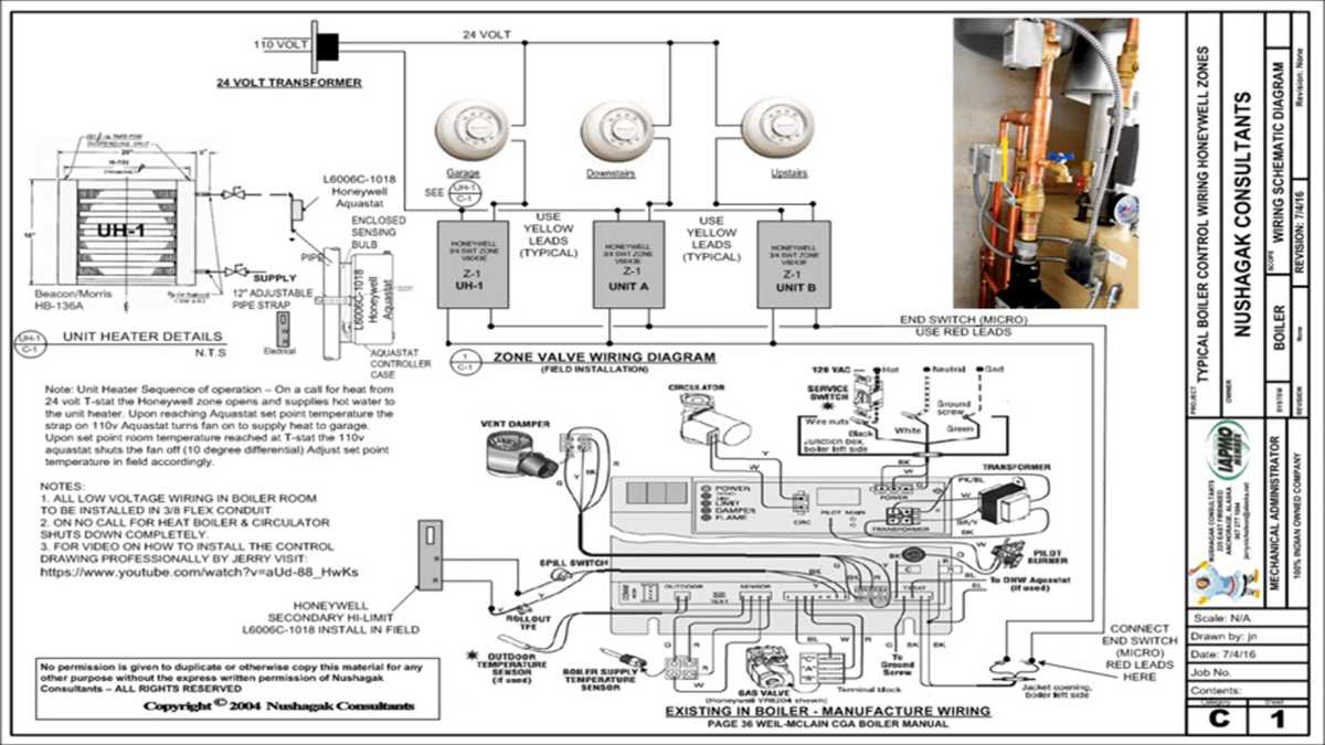
Control valve wiring diagrams are essential for understanding and troubleshooting the electrical connections of control valves. These diagrams provide a visual representation of how the different components of a control valve are wired together to facilitate the control of fluid flow in a system. By understanding these diagrams, engineers and technicians can better diagnose and repair control valve issues.
The control valve wiring diagram typically includes information about the power supply connections, such as voltage and frequency, as well as the types of signals being used for control, such as analog or digital signals. It also shows the wiring connections for the actuator, positioner, and any other auxiliary devices that may be present, such as limit switches or solenoid valves.
One of the key elements in a control valve wiring diagram is the terminal strip. This strip is used to connect the various wires from different components to create a complete electrical circuit. The diagram will indicate which terminals on the strip correspond to specific components or signals, making it easier to identify and troubleshoot any wiring issues.
It’s important to note that control valve wiring diagrams can vary depending on the specific manufacturer and model of the control valve. Therefore, it’s crucial to consult the appropriate documentation provided by the manufacturer when working with a specific control valve. This documentation will typically include detailed wiring diagrams, along with instructions on how to interpret and use them effectively.
In summary, understanding control valve wiring diagrams is crucial for anyone involved in the installation, operation, or maintenance of control valves. These diagrams provide valuable information about the electrical connections and components of a control valve, enabling efficient troubleshooting and repair of control valve issues.
What is a Control Valve?
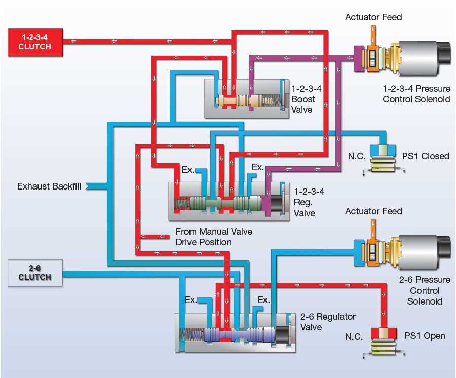
A control valve is a device that regulates and controls the flow of fluid (liquid or gas) in a process system. It is an important component in various industries such as oil and gas, chemical, power generation, and water treatment. The control valve ensures that the fluid flow or pressure is maintained at the desired level and can be adjusted based on the requirements of the system.
A typical control valve consists of a valve body, actuator, and positioner. The valve body contains an orifice or a passage through which the fluid flows. The actuator is responsible for opening and closing the valve, while the positioner controls the position of the valve to achieve precise control. The control valve is usually controlled by a controller or a computer system that sends signals to the actuator and positioner to adjust the valve position based on the setpoint or desired flow rate.
Control valves are available in various types and designs, including globe valves, butterfly valves, and ball valves. Each type has its unique characteristics and is suitable for different applications. For example, globe valves are commonly used for throttling and regulating flow, while butterfly valves are often used for on-off control. Control valves can also be equipped with additional features such as pressure and temperature sensors, smart positioners, and digital communication interfaces for advanced control and monitoring.
In summary, control valves play a crucial role in maintaining the desired flow rate and pressure in industrial processes. They enable precise control and adjustment of fluid flow, which is essential for efficient and safe operation of various systems. Choosing the right control valve for a specific application requires considering factors such as flow rates, pressure drops, fluid characteristics, and system requirements.
Why is Control Valve Wiring Important?
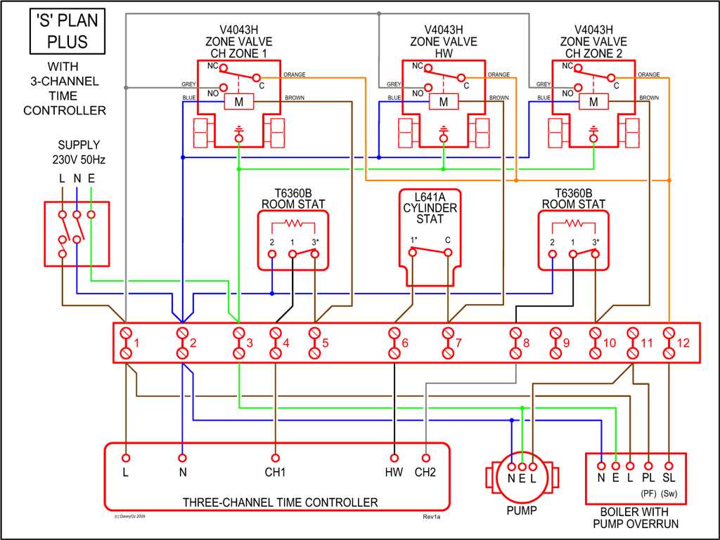
Control valve wiring plays a crucial role in the efficient operation of control valves, which are widely used in various industries to regulate fluid flow. Control valves are used to control the pressure, temperature, and flow rate of fluids in pipelines, and their wiring is essential to ensure accurate and reliable control.
Proper control valve wiring ensures that the control signal from the control system is transmitted correctly to the valve actuator, allowing it to open or close to the desired position. This wiring includes the connection of power supply, control signals, and feedback signals between the control system, valve positioner, and actuator. A well-designed and correctly installed wiring system ensures that the control valve responds accurately and promptly to the control system’s commands.
1. Eases Maintenance and Troubleshooting: Control valve wiring simplifies maintenance and troubleshooting processes by providing clear and organized connections. Properly labeled and documented wiring diagrams make it easier for technicians to identify and rectify any issues that may arise, reducing downtime and minimizing production interruptions.
2. Ensures Safety: Control valve wiring adheres to safety standards and guidelines, preventing potential hazards. Proper grounding and insulation techniques protect personnel and equipment from electrical shocks, short circuits, and fires. Compliance with electrical codes and regulations guarantees the safety of the control valve system.
3. Enhances Efficiency: Accurate and reliable control valve wiring improves the overall efficiency of the control system. Precise control of fluid flow, pressure, and temperature translates into optimized production processes, reduced energy consumption, and cost savings. Properly calibrated and maintained control valves contribute to smooth operations and increased productivity.
In conclusion, control valve wiring is vital for the proper functioning and performance of control valves. It ensures accurate transmission of control signals, simplifies maintenance and troubleshooting, enhances safety, and improves the overall efficiency of control systems. Paying attention to control valve wiring is crucial for industries that rely on precise and reliable fluid control.
Basic Components of a Control Valve Wiring Diagram

A control valve wiring diagram is a schematic representation of the electrical connections and components of a control valve system. It is used to understand and troubleshoot the wiring of the control valve, ensuring proper operation and functionality. Several important components are typically included in a control valve wiring diagram.
1. Control Valve: The control valve itself is the main component of the system. It regulates the flow of fluid or gas and is controlled by the electrical signals received through the wiring diagram.
2. Actuator: The actuator is responsible for moving the valve stem or shaft to open or close the control valve. It is typically operated by an electrical or pneumatic signal received from the wiring diagram.
3. Power Supply: The power supply provides electrical energy to the control valve system. It is usually indicated in the wiring diagram, specifying the voltage and current requirements for proper operation.
4. Controller: The controller is the device that sends electrical signals to the actuator, determining the desired position of the control valve based on the input signals it receives. It is an important component of the control valve wiring diagram.
5. Sensors: Sensors are used to measure various parameters such as flow rate, pressure, temperature, or level, depending on the application. These sensors provide input signals to the controller, which then adjusts the position of the control valve accordingly.
6. Wiring Connections: The wiring connections in the control valve wiring diagram show how the different components are electrically connected. This includes the connections between the power supply, controller, sensors, actuator, and the control valve itself.
In summary, a control valve wiring diagram includes the control valve, actuator, power supply, controller, sensors, and wiring connections. It provides a visual representation of the electrical system, ensuring the proper functioning and operation of the control valve system.
Wiring Diagram Symbols
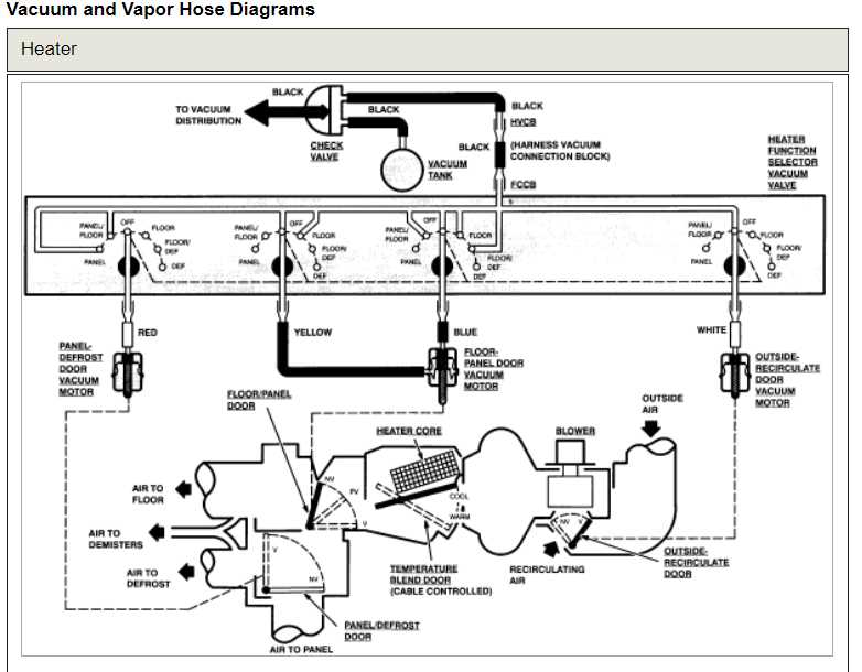
When it comes to understanding control valve wiring diagrams, it is important to be familiar with the symbols used to represent various components and connections. These symbols help to facilitate clear communication and understanding of the wiring diagram.
Here are some commonly used symbols found in control valve wiring diagrams:
- Coil symbol: This symbol represents the coil of a solenoid valve or electromagnet. It typically consists of a rectangle with a diagonal line inside.
- Contact symbol: This symbol is used to represent contacts in electrical circuits. It can be either normally open (NO) or normally closed (NC). The NO contact is represented by a circle and the NC contact is represented by a circle with a diagonal line inside.
- Power supply symbol: This symbol represents the power supply to the control valve. It is usually represented by a straight line with a junction at the end.
- Ground symbol: This symbol represents the ground connection. It is usually represented by three horizontal lines.
- Transformer symbol: This symbol is used to represent a transformer in the control valve circuit. It is typically represented by two circles connected by a line.
These symbols are just a few examples of the many symbols used in control valve wiring diagrams. It is important to consult the wiring diagram legend or reference materials to fully understand the meaning of all the symbols used in a specific diagram.
Step-by-Step Guide to Reading Control Valve Wiring Diagrams
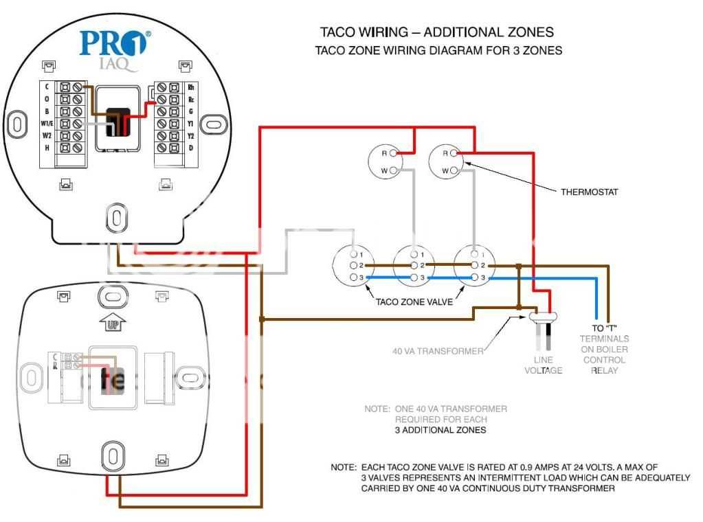
Control valve wiring diagrams are essential for understanding the electrical connections and control signals involved in operating a control valve. These diagrams provide a visual representation of how the various components of a control valve system are interconnected, making it easier to troubleshoot and maintain the system.
1. Familiarize yourself with the symbols: Control valve wiring diagrams use symbols to represent different electrical components and connections. It is important to understand the meaning of these symbols to correctly interpret the wiring diagram. Common symbols include switches, relays, transformers, and various types of connections.
2. Identify the power source: The first step in reading a control valve wiring diagram is to locate the power source. This is usually shown as a battery symbol or an AC power symbol. Understanding the power source is crucial as it determines the voltage and current the control valve operates on.
3. Trace the control signal flow: Control valve wiring diagrams show how the control signal travels from the controller to the valve actuator. Follow the lines or arrows in the diagram to understand the path of the signal. This will help identify any potential wiring issues or malfunctions along the control signal flow.
4. Check for switches and relays: Look for symbols representing switches and relays in the wiring diagram. These components control the flow of electricity to the valve actuator based on the control signal received. Understanding how these switches and relays are connected and their function is essential for troubleshooting and maintenance.
5. Note the valve actuator connections: The wiring diagram will also show the connections between the valve actuator and the control system. Pay attention to the symbols representing the actuator and note how it is connected to the power source and the control signal. This information is crucial for understanding how the valve actuator operates.
6. Consider safety precautions and standards: When reading control valve wiring diagrams, it is important to keep in mind safety precautions and standards. Follow any safety guidelines provided and make sure to adhere to electrical codes and regulations to ensure the safe operation of the control valve system.
Overall, reading control valve wiring diagrams requires a basic understanding of electrical symbols and connections. By following these step-by-step guidelines, it becomes easier to interpret and troubleshoot control valve wiring diagrams, ensuring the efficient and reliable operation of control valve systems.
Common Issues and Troubleshooting in Control Valve Wiring
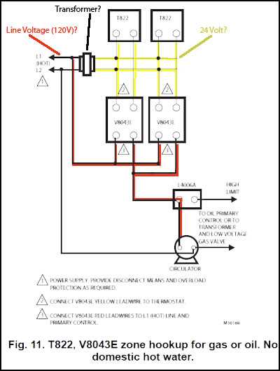
Control valve wiring plays a crucial role in the proper functioning of control systems. However, like any other electrical system, it can encounter various issues that may affect its performance. Understanding common problems and learning how to troubleshoot them can help ensure the smooth operation of control valves.
1. Loose or damaged wiring
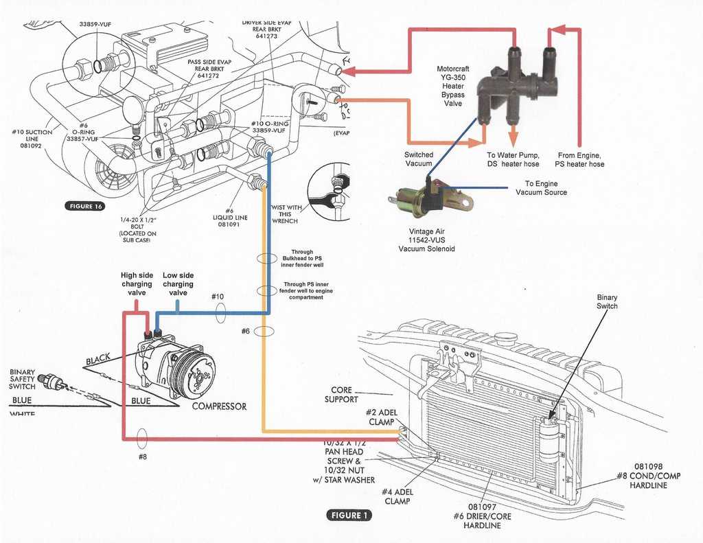
A common issue in control valve wiring is loose or damaged wiring connections. Loose connections can cause intermittent or total loss of control signal, leading to valve malfunctions or failure. Similarly, damaged wiring can result in short circuits, open circuits, or electrical leakage, compromising the performance of the control valve.
To address loose or damaged wiring, it is important to regularly inspect and secure all wiring connections. This includes ensuring that the terminal screws on the control valve and the terminal blocks in the control panel are tightened properly. Additionally, damaged wiring should be repaired or replaced promptly to prevent further issues.
2. Miswiring
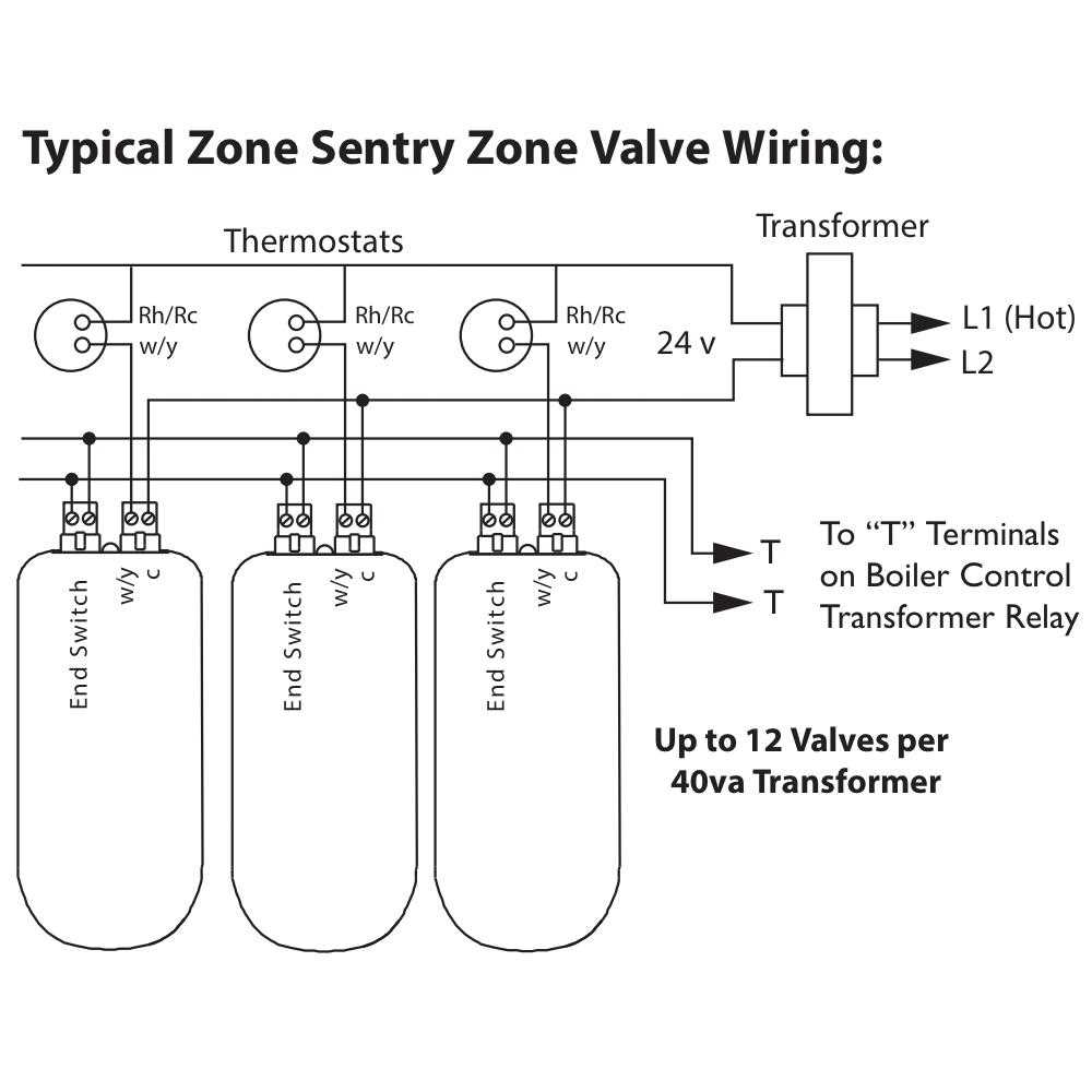
Miswiring occurs when the control valve is not wired correctly, leading to improper operation or complete failure. This can happen due to human error during installation, maintenance, or modifications of the control system. Common miswiring issues include connecting wires to the wrong terminals, reversing polarity, or incorrect wiring of control signals.
To troubleshoot miswiring, it is essential to refer to the control valve wiring diagram provided by the manufacturer. Carefully compare the diagram with the actual wiring connections and correct any discrepancies. Additionally, double-checking the wiring against the control system’s documentation or consulting with an expert can help identify and rectify miswiring issues.
3. Grounding problems
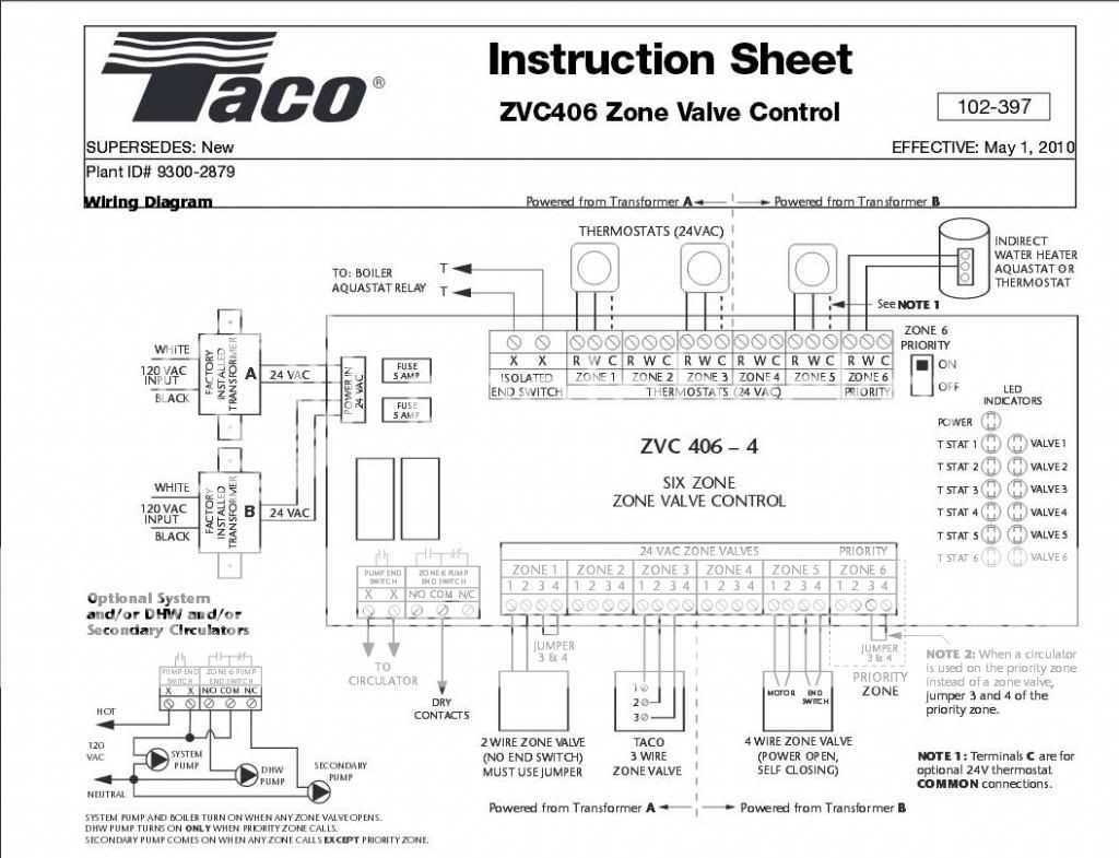
Improper grounding can lead to various issues in control valve wiring, such as electrical noise interference, unstable control signals, or even damage to the control equipment. Grounding problems can occur due to inadequate grounding or improper grounding techniques, such as using incorrect ground wire size or failing to establish a proper ground connection.
To troubleshoot grounding problems, it is vital to ensure that the control valve and the control panel are correctly grounded according to the manufacturer’s guidelines. This includes using the recommended ground wire size, establishing a solid ground connection to a reliable ground source, and minimizing the length of ground wires. Regularly inspecting the grounding system and addressing any issues promptly can help prevent grounding-related problems.
Summary
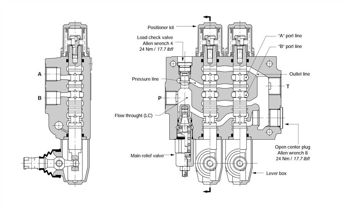
Control valve wiring can encounter various issues, including loose or damaged wiring, miswiring, and grounding problems. Regular inspections, secure wiring connections, and proper adherence to wiring diagrams can help prevent these issues. Timely troubleshooting and addressing any problems that arise can ensure the efficient and reliable operation of control valve systems.
Q&A:
What are common issues in control valve wiring?
Common issues in control valve wiring include loose or corroded connections, improper wire sizing, mislabeling of wires, and incorrect electrical grounding.
How can loose or corroded connections in control valve wiring be fixed?
Loose or corroded connections can be fixed by tightening the terminal screws or using electrical contact cleaner to remove corrosion. In some cases, the affected wires may need to be replaced.
What can happen if the control valve wiring has improper wire sizing?
If the control valve wiring has improper wire sizing, it can lead to overheating, voltage drop, and inefficient operation of the control valve. This can result in erroneous valve positions and unreliable control of the process.
How can mislabeling of wires in control valve wiring be resolved?
Mislabeling of wires in control valve wiring can be resolved by properly identifying and relabeling the wires. This can be done by referring to the control valve wiring diagram or documentation provided by the manufacturer.