
CT connection is taken from the main incomer side of transformer, after the fix compensation of transformer. Power factor controller .
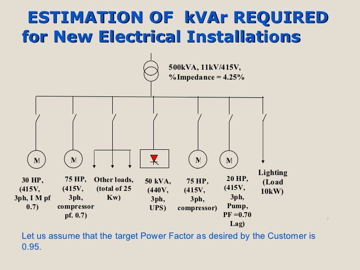
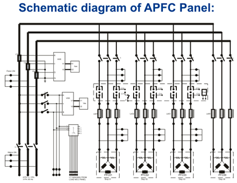
Note that APFC panel can maintain the power factor on L.T side of transformer and it is necessary to. Detailed Capacitor Connection Diagrams for KVAR power factor correction units.
be installed on the distribution system ahead of the motor controller, and must not be switched with the load motor. DISTRIBUTION PANEL. automatic control of capacitor banks in 3 phase 4 Fig.1 Wiring diagram of RPM- 14 relay on APFC panel.
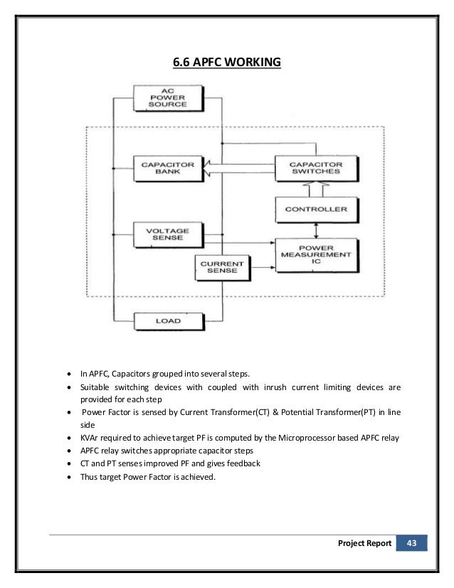
(a) Auxiliary supply to RPM Please connect. tomatic Power Factor Controller (APFC) is to be . diagram at the rear side of APFC controller.
4. .
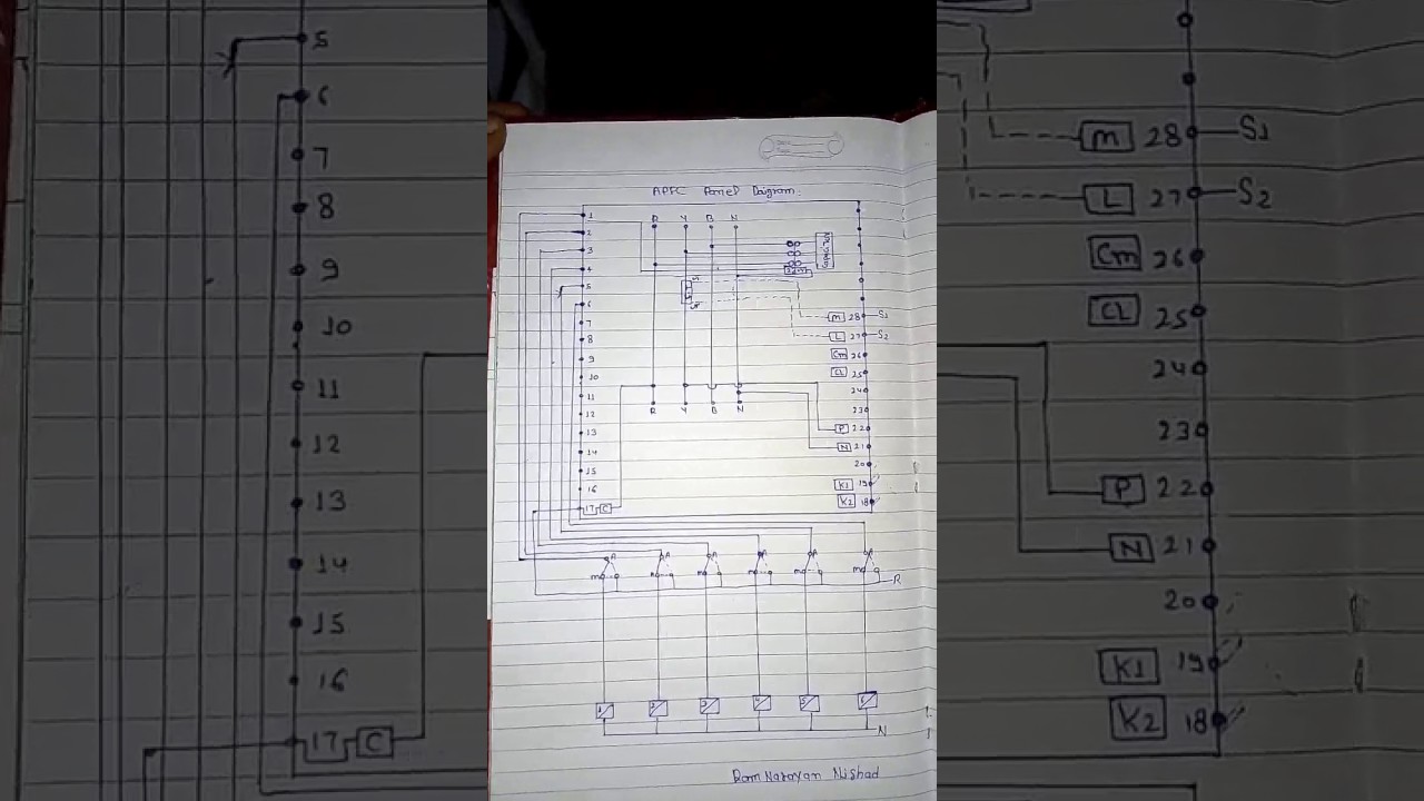
connection for the APFC Panel. 3.
After installation of LECS APFC panel We specialize in Reactive power management,. Harmonics .
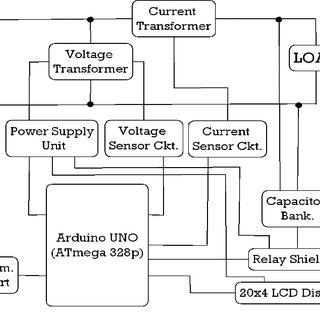
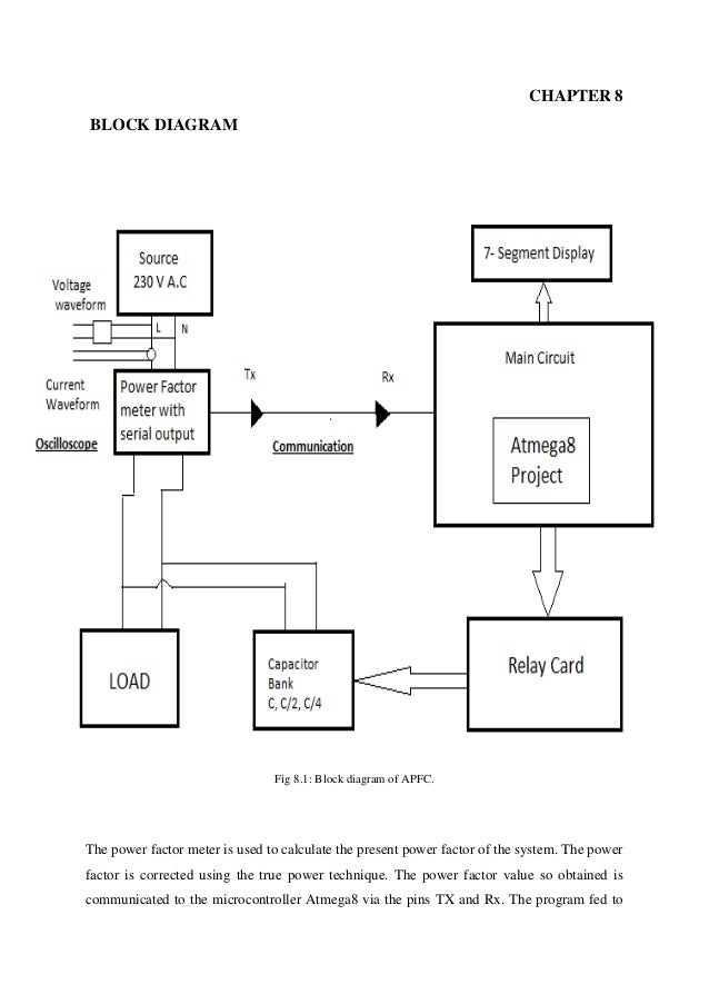
Automatic power factor controller using pic microcontroller
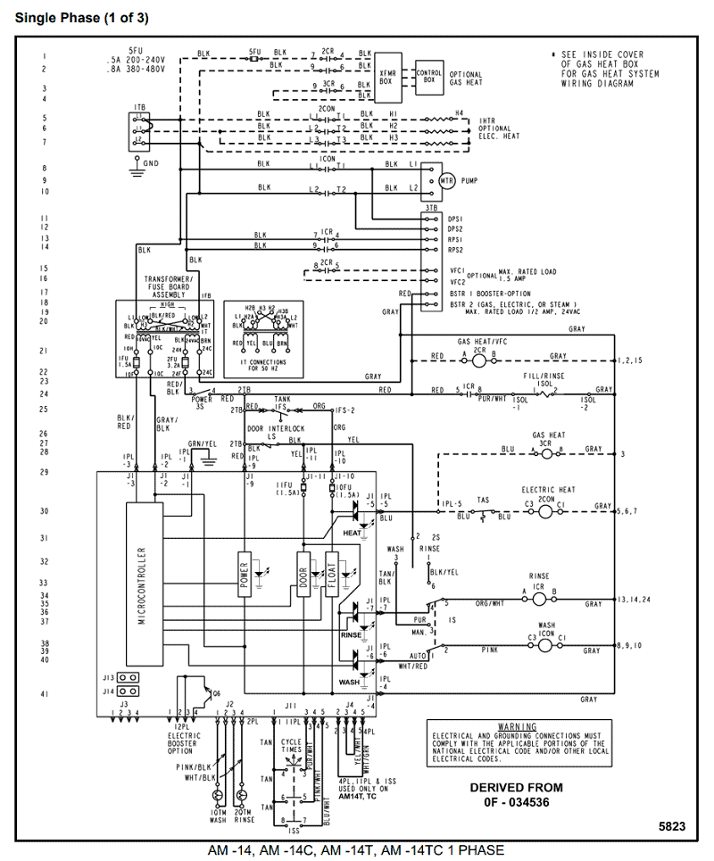
The diagram (Fig.3) shows that a series resonant circuit.Capacitor Panel Wiring Diagram – 98 4runner Wiring Diagram, 4l60e Wiring Diagram, Crossfire Wiring Harness, 93 Mustang Wiring Diagram, Alfa Romeo Engine Wiring Diagram, Armstrong Oil Furnace Wiring Diagram, Ford Escape Wiring Diagram, Volkswagen Air Conditioning Wiring Diagram, Audio Cable Wiring Diagrams, Basic Solar Wiring Diagram. Industrial Control Wiring Guide Second edition Bob Mercer OXFORD AUCKLAND BOSTON JOHANNESBURG MELBOURNE NEW DELHI.
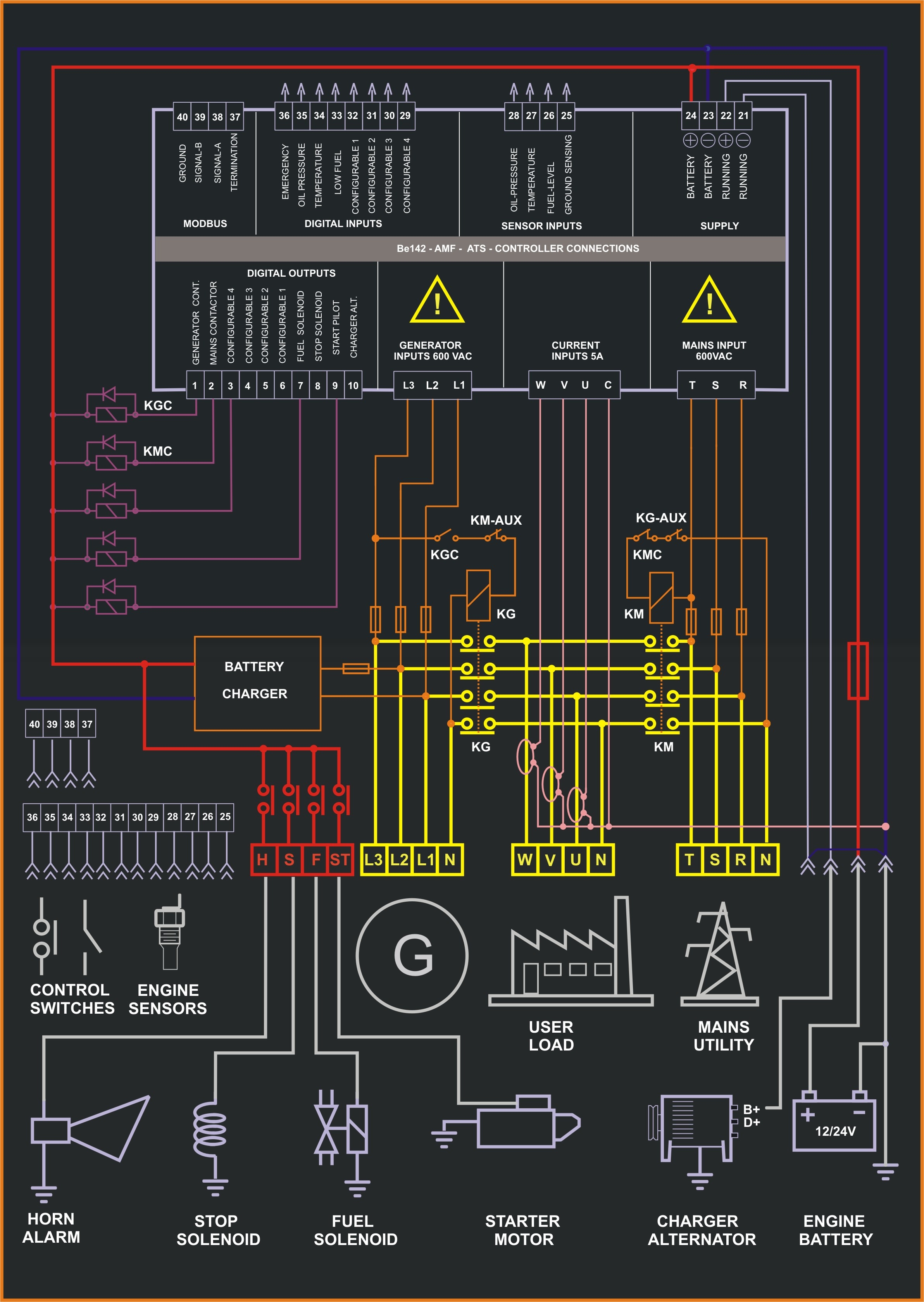
Newnes An imprint of Butterworth-Heinemann Linacre House, Jordan Hill, Oxford OX2 8DP Wildwood Avenue, Woburn, MA A division of Reed Educational and Professional Publishing Ltd. Be2K-Plus AMF panel control wiring — Consult Section for software upgrades & revisions The information in this document may be subject to change without notice.
The system will all be low voltage to save on wiring costs. We now have the information to begin a wiring diagram. (We are not going to pick the devices by number that we need to do this job.
Generic nomenclature will suffice, since we are demonstrating the making of a wiring diagram). The system will all be low voltage to save on wiring costs. We now have the information to begin a wiring diagram.
(We are not going to pick the devices by number that we need to do this job. Generic nomenclature will suffice, since we are demonstrating the making of a wiring diagram).Connection Diagrams for Factor Correction Capacitors | KVAR GuideIndex of /schematron.org
