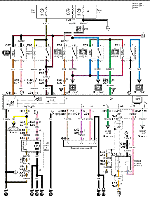
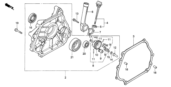
The new device is a Cooper Wiring W-BOX Combination device with a . and wiring diagrams about wiring light switches describing the most common. TR & TR Wiring Diagrams – Cooper Wiring Devices Triple Deco Single Pole Switch.
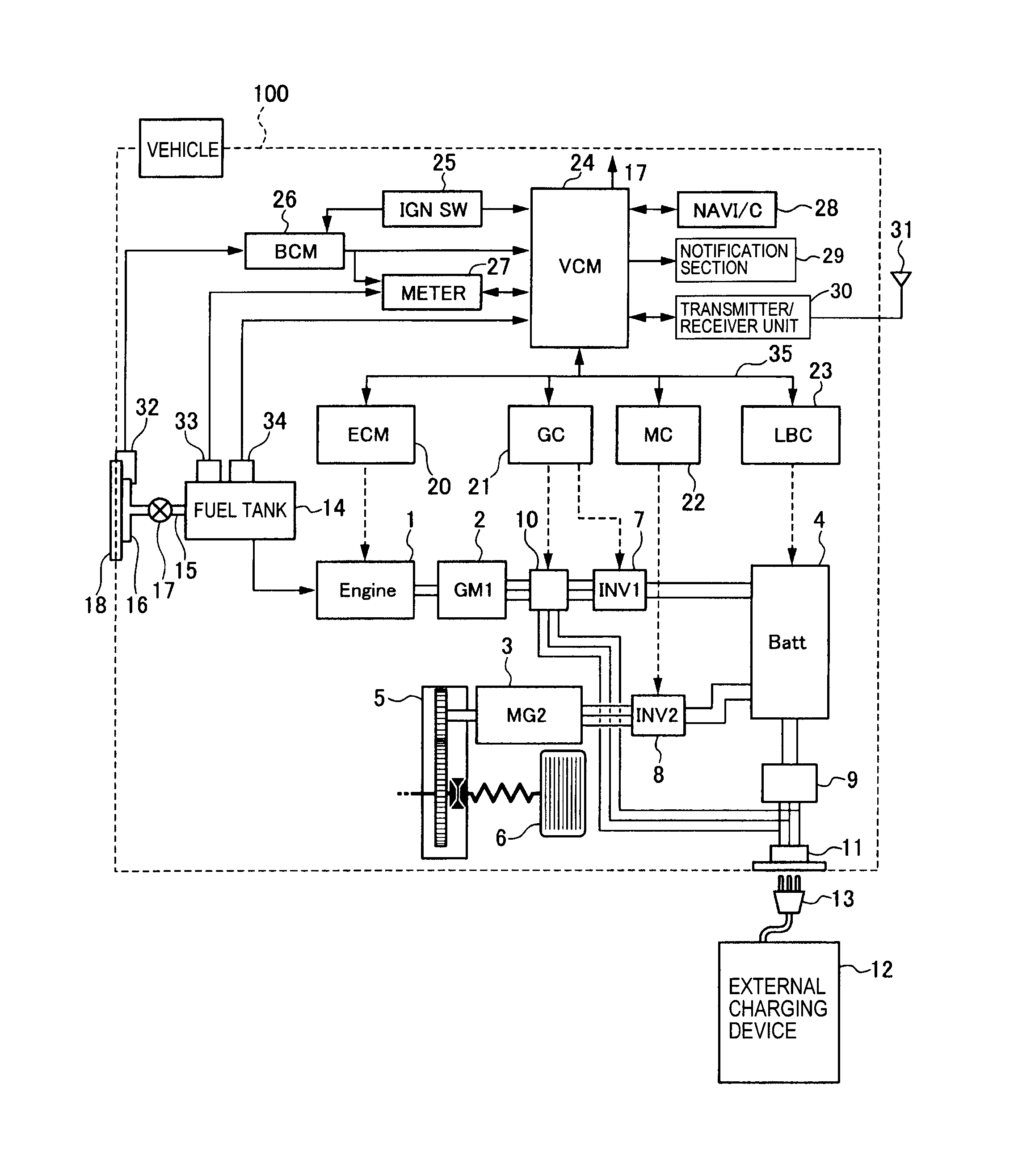
Combo switches require Neutral wire in the box. Neutral wires are usually the white wires twisted together, covered with wire nut, and pushed to back of box.
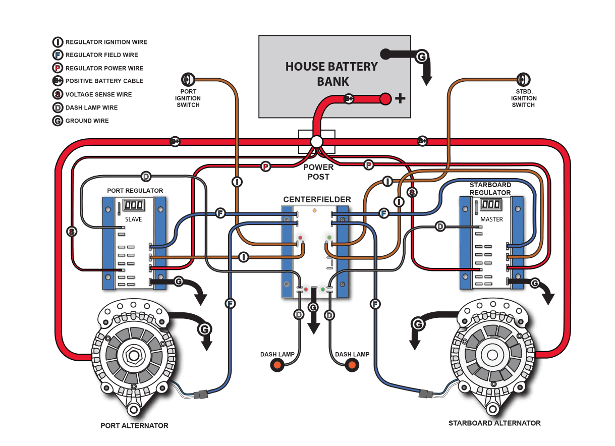
TR features a neon pilot light which is On when switch is On. Switch is Break-off provision for wiring both devices on the same circuit or on separate circuits. Cooper light switch wiring diagram tr is a sideways rocker switch and the light is in the top we have around a dozen such devices in my.
Tamper Resistant Toggle Combination Switch/Receptacle – TR, TR · Tamper Resistant Toggle Combination Switch/Receptacle – TRThe Eaton TRW Combo Single-Pole Switch with Tamper Resistant 2-Pole, 3-Wire Receptacle is a convenient and resourceful amenity to have in your home that offers simple solutions/5(). Printable copies of Mini Cooper Wiring Diagrams.
I tow a Mini behind a motor home (standard shift), and I want to install a the light kit so the Mini lights (tail, turn and brake) will . Decorator Combination Devices – , , , Tamper Resistant Toggle Combination Switch/Receptacle – TR, TR Toggle Combination Pilot Light Switch – , Tamper Resistant Decorator Combination Devices – TR Dimmable LED Nightlight Combination with Switch – Toggle Combination Switches – , , Terminal screws are backed out and ready for wiring to enhance ease of installation. Break-off provision for wiring both devices on the same circuit or on separate circuits.
Triple wipe blade contacts and double wipe ground contacts ensure long-term plug retention on receptacles. SYSTEM WIRING DIAGRAMS MINI – Cooper USING MITCHELL1’S WIRING DIAGRAMS For information on using these wiring diagrams, see USING MITCHELL1’S SYSTEM WIRING DIAGRAMS article. AIR CONDITIONING MINI Cooper S SYSTEM WIRING DIAGRAMS MINI – Cooper .SOLVED: I”m installing a Cooper Devices – FixyaSOLVED: TR & TR Wiring Diagrams – Fixya
