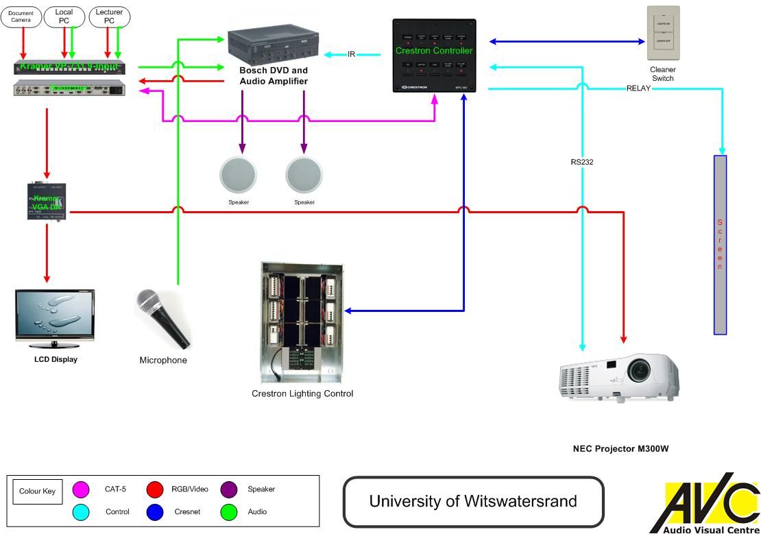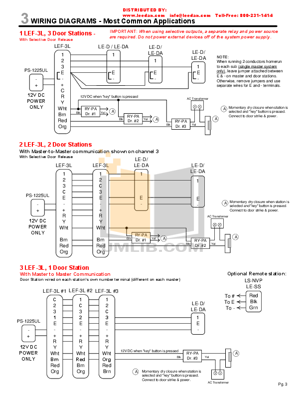
The CLW-DIMSWEX-E is a W/VA in-wall dimmer/switch combo and programmable Although functional as a standalone dimmer or light switch, the CLW-DIMSWEX-E delivers Wire the device as shown in the following diagram.
Crestron simplifies design, installation, and startup of commercial lighting control with Zūm Lighting Control . Dimmers and Switches . Application Diagrams.
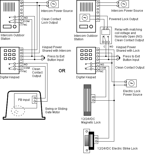
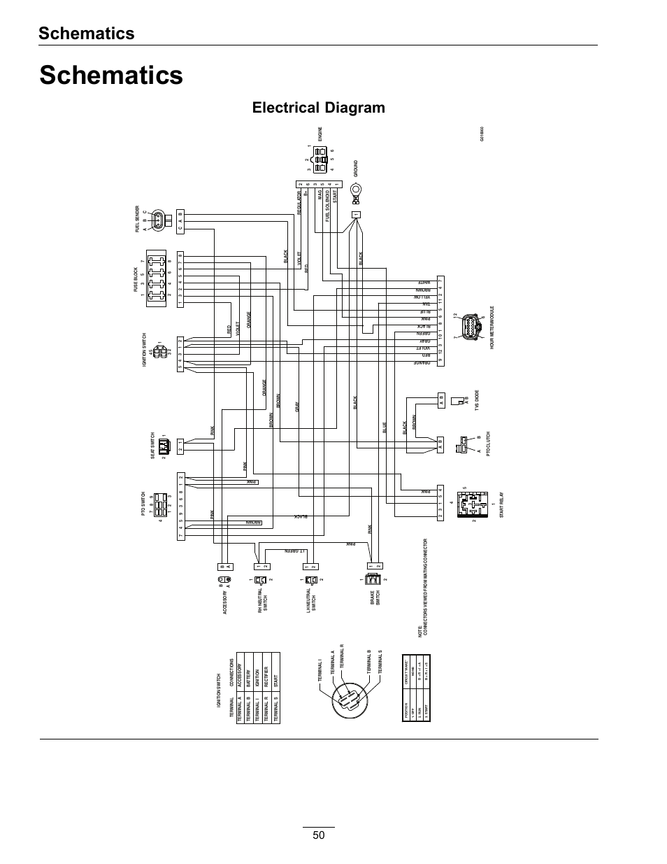
switch control point in a multi-switch / single circuit application. light emitting diode (LED) with software adjustable . Wiring Diagram of CLW device to Cresnet.
Page 1 of CWD Wall Type Dimmer User Manual Description Crestron Electronics Inc Button and Switch” on page 4 for more information on customizing light levels. .
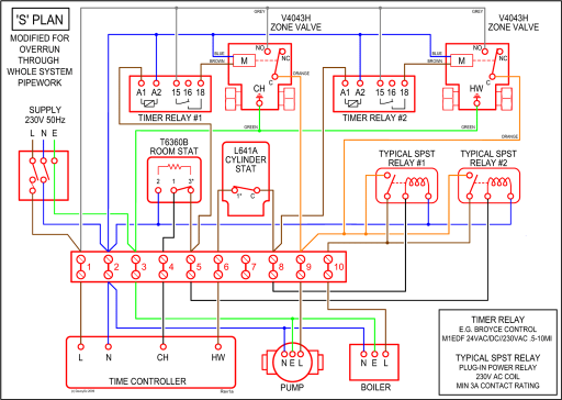
Wiring Diagram of CLW-DIMS1RF with multiple CLWSLVD1RFs. The following diagram shows CRESTRON GREEN LIGHT EXPRESS power .
other devices that provide a dry contact closure (manual switch, fire alarm relay.Crestron’s recommends using only Crestron certified wire and cable for project installations. If Crestron certified wire and cable is not used and technical on-site support is required to troubleshoot a problem caused by improper wiring, a support charge may be incurred. 4 light switch box gang on single plate diagram,wy originl 4 gang light switch 2 dimmer on single plate panel,4 gang light switch wiring diagram switches 1 riddle way, 4 hole light switch plate toggle way wiring diagram, 4 way light switch diagram uk wiring gang 2,4 gang light switch. Crestron CLTI-1MC4 Installation Manual.
(left or right) wiring label to the Crestron Automation Enclosure. The wiring label lies beneath the terminal block as shown in the two wiring diagrams on this page.
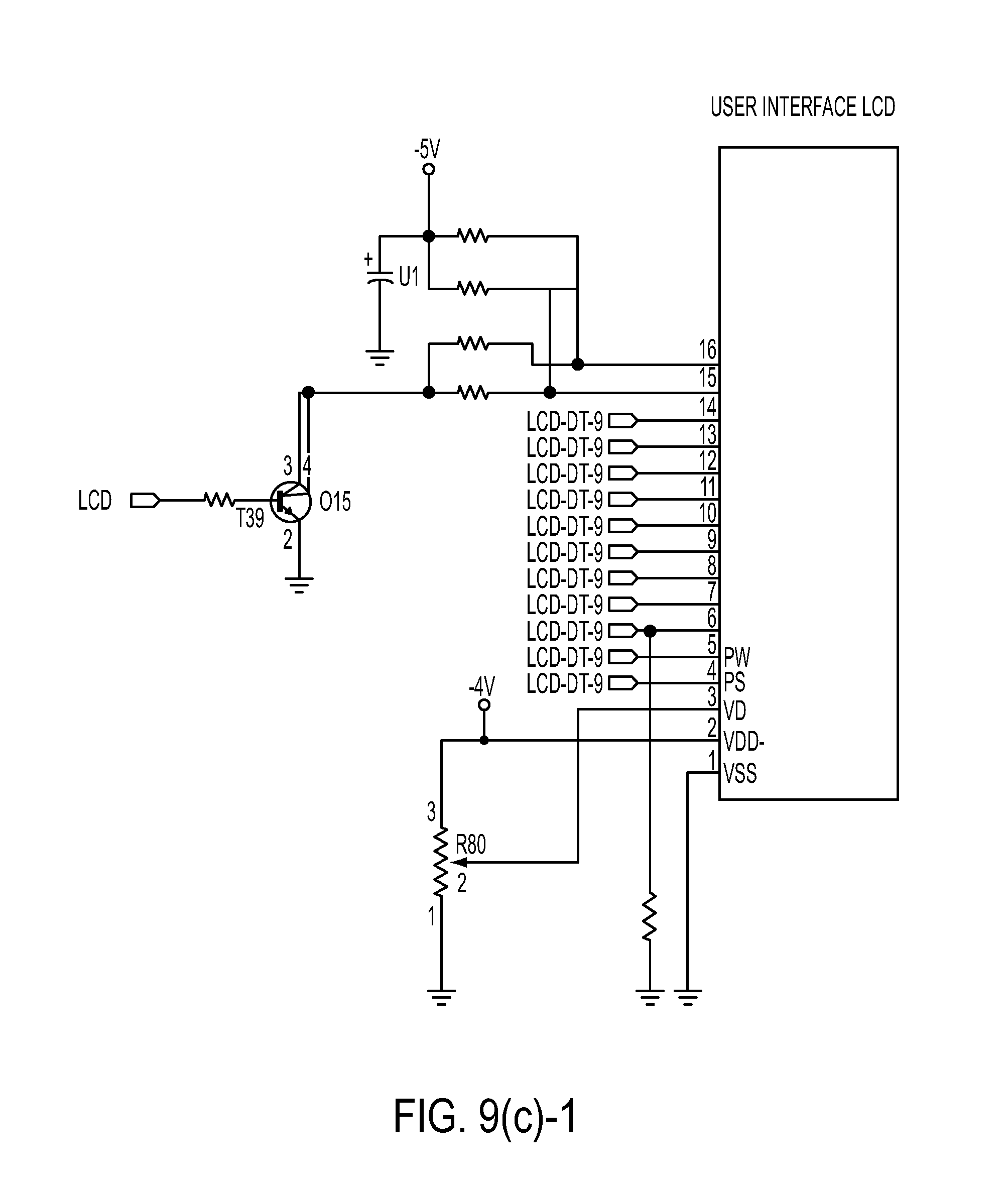
Page 3. 4.
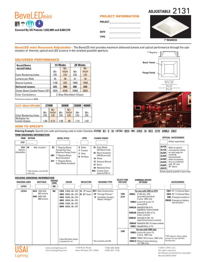
Turn on the circuit breaker and verify that the green PWR LED on the module lights and the breaker does not trip. Wireless Switch Installation Guide wire nuts according to the relevant wiring diagram. See “Sample Wiring Configurations.” • Ensure that at least one (1) LED on the face of the Switch is lit.
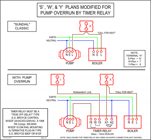
• Ensure that the light bulb is not burned out and is screwed on tightly. nLIGHT ZONE COMMUNICATION CAT5e • Each nLight zone has 16 unique switch groups, 16 occupancy groups, and 16 photocell groups that can be assigned as needed to achieve the desired functionality for a zone: ―Separate wall controls for each row of lights ―Multiple daylight dimming zones • These groups are also referred to as the.Crestron Green Light – Lighting – Design IntegrationCrestron Lighting Panels Wiring Diagrams – schematron.org
