CLS-C6M. iLux™ Integrated.
Crestron Digital Media
Lighting System. CAEN.
Automation. Enclosure.
Crestron RoomView®. Remote Asset Management. CLS-C6M.

iLux™ Integrated. What type and gauge of cable should I use for connecting Crestron Cresnet network devices?
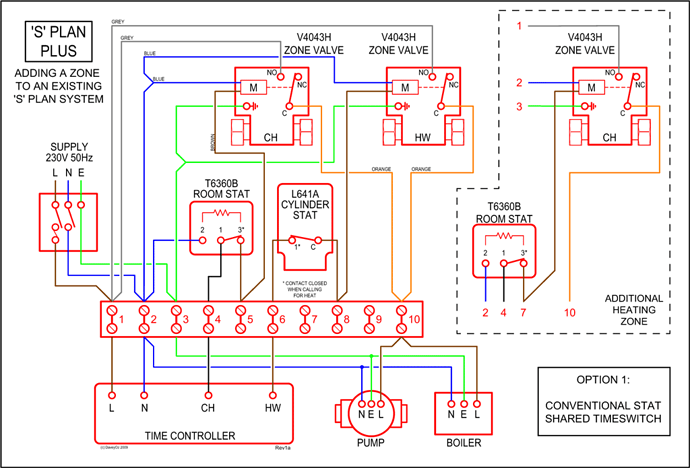
Specification for Cresnet network wiring is 2 twisted pair, 1 pair #18AWG For 22awg wire, R = 15, as per the Diagram below. Computer. Computer.
HDTV. Receiver.

HDTV. Receiver schematron.org NOTE: For conceptual purposes only.
Not a wiring diagram. DVPHD.
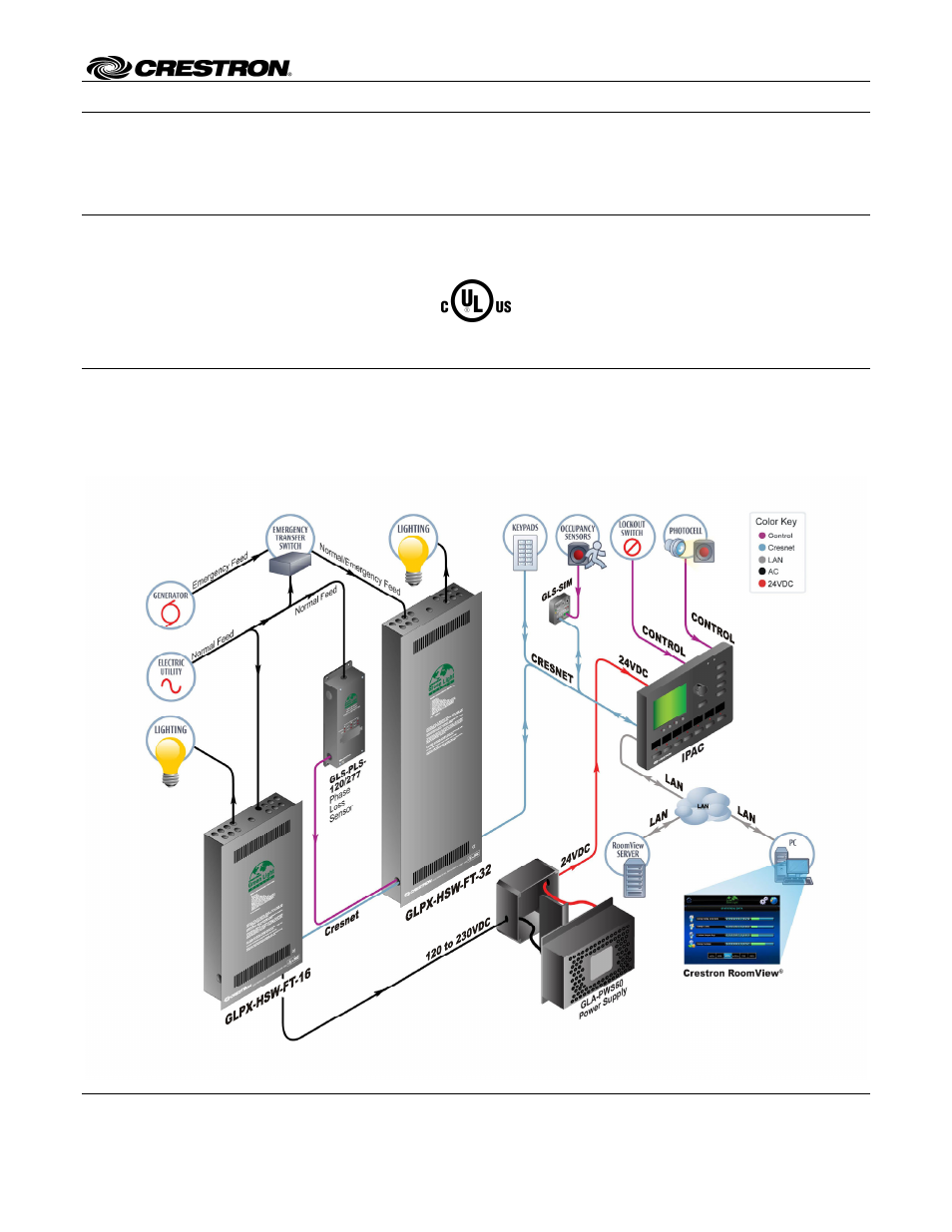
RESIDENTIAL LIGHTING WIRING PLAN. ..
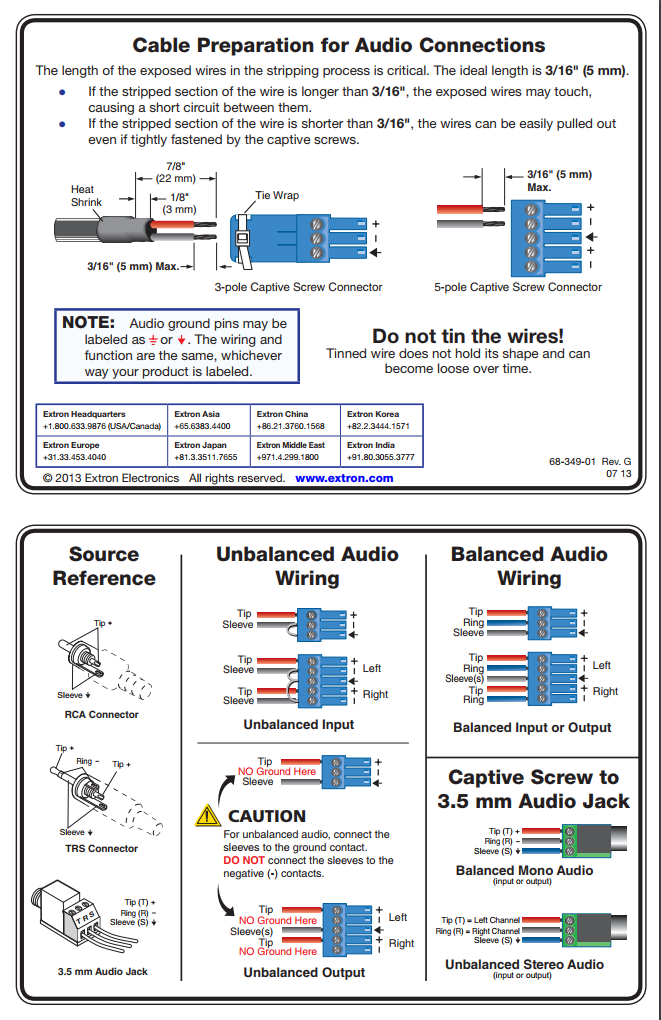
Cresnet® low-voltage wiring and/or RF control can be used .. The complete diagram is available on line at.
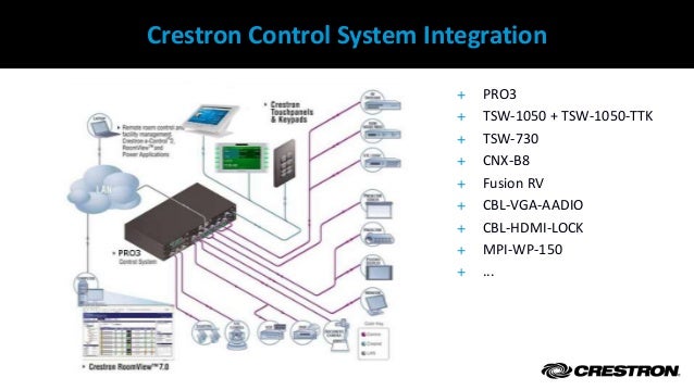
The following diagram shows a C2N-UNI8IO in a lighting and AV system application. Wiring Diagrams. CAUTION: Shorting non-current limited supplies may.Thermostats Crestron CHV-TSTAT and CHV-THSTAT Quick Installation Reference 1.
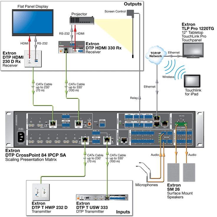
How to create a Crestron Control System overview by using a Topology Diagram
Select a suitable location and run the connecting wires from the heating/cooling system and the Cresnet system. Refer to page 5 for a description of the thermostat connectors. Refer to page 7 for Network wiring details.
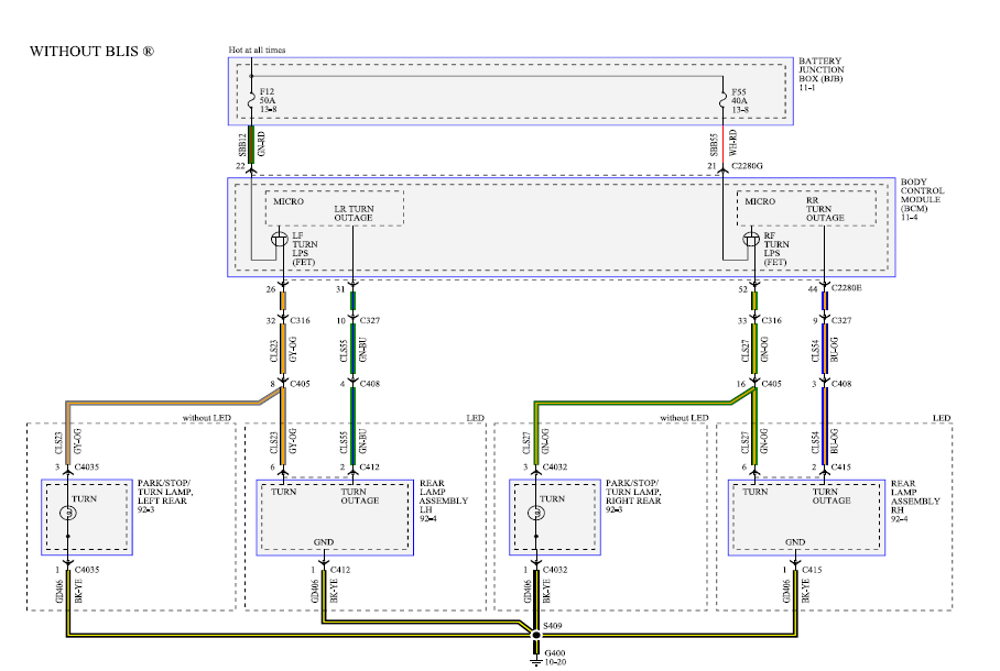
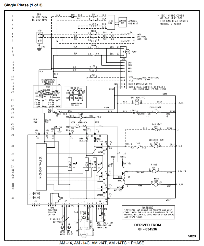
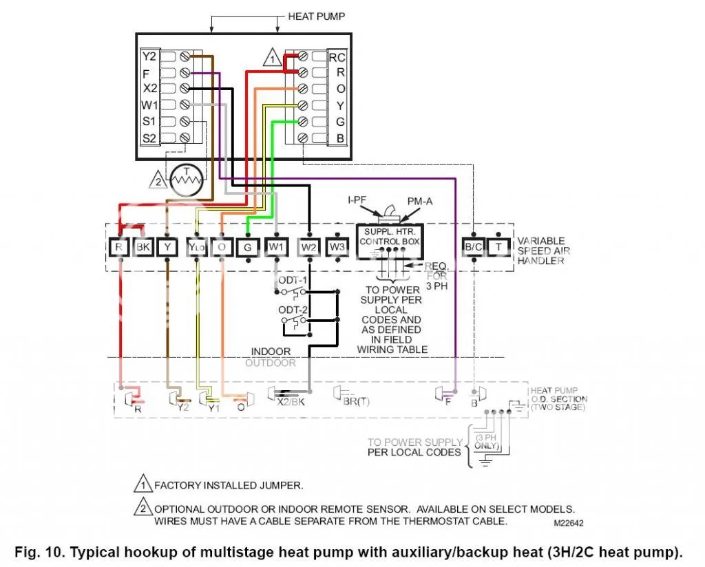
Use the appropriate wiring diagram. Crestron Electronics, Inc. Installation Guide – DOC.
Design Machine and Crestron
A 15 Volvo Drive Rockleigh, NJ () Refer to the following diagram when making connections to the device. 3. Push all power wires back into the electrical box and fasten the device to the electrical WIRING DIAGRAMS REPLACE 3-WAY SWITCH WITH CLW-SLV-P REPLACE 3-WAY.
Crestron GLS-OIR-C/ DESCRIPTION Infrared Ceiling Mounted The Occupancy Sensor is a low-voltage infrared sensor that works with the Occupancy Sensor other compatible interface) can be configured via software, but the sensor is typically used to turn lights on when a room Operations &. Crestron Cls C6 Wiring Diagram Operations Guide – DOC.
We know from our users’ experience that most of. or by the circuitry of the control device, or inadvertently in the wiring the current on the control bus will be less than mA. SIGNAL CRESTRON SOMFY RJ45 RX TX GND A (-) B (+) 2 3 5 3 6 8 SOMFY DB9 2 3 NOTE: AMX NetLinx Serial Ports are wired for both RS & RS It will NOT communicate with both protocols simultaneously.

If RS communication is used, the RS connections(A and B) should be omitted. Conversely, if RS is used, the RX and TX.Crestron Green Light – Lighting – Design IntegrationCrestron’s New Commercial Lighting Control Plan – rAVe [Publications]
