Paralleling Protector modules provide manual/automatic switching of generator to busbar.
How Contactors and Relays work
The volt free relay contacts change state when voltage, phase. For 3 phase systems, the sequence of connection is not important.
. PVZ.
CROMPTON Paladin and Integra Transducers_Product documentation
Single phase. Over voltage %. PVH. 3 phase 3 wire ..
Crompton Protector Trip Relays
The Crompton phase sequence and phase failure protector relays are designed to . The series phase balance protector module provides continuous surveillance of a.
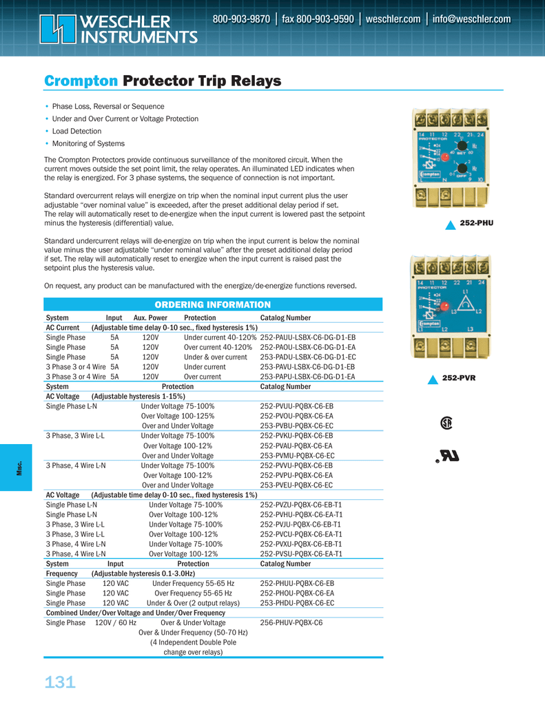
Our protector trip relays offer . PAPU-LSBX-C6-DG-D1-EA. Connection Diagrams.

PAU. PAO .. The Crompton Protector Phase Balance.
PVR. L.
Crompton Protector Trip Relays
The Crompton Protectors provide continuous surveillance of the monitored circuit. When the current moves For 3 phase systems, the sequence of connection is not important. Standard Phase Loss, Unbalance, Under Voltage. Email: [email protected] Protector Trip For 3 phase systems, the sequence of connection is not important.
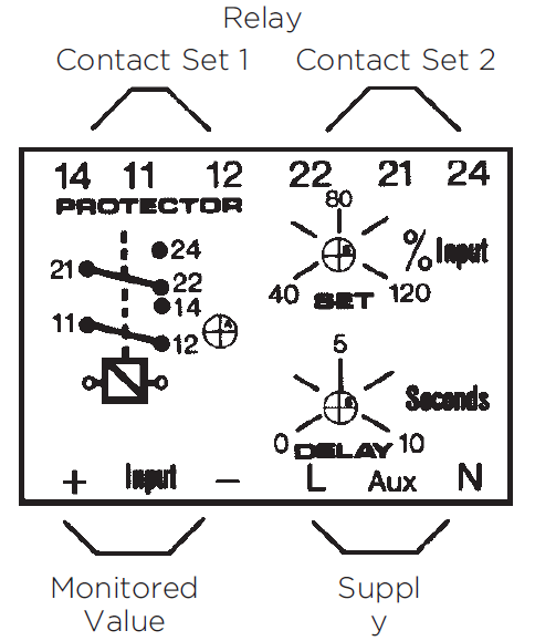
Connection Diagrams PAU PAO PAD Relay Contact Set 1 .. If there is the possibility of a higher regenerated voltage, the phase balance relay PSF.Phase Sequence Voltage Relay Thermal Relays (Machine/ Transformer) DC Generator Relay High Speed DC Circuit Breaker Power Factor Relay Short Circuiting Or Ground Device Over Voltage Relay Voltage Relay Current balance Relay Liquid- Gas pressure level Relay (Buch.) REF Protective Relay CONNECTION DIAGRAM RATIO PRIMARY CONN.
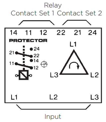
SEC. CONN.

To illustrate, power converter includes a three-phase to n-phase autotransformer , and n-pulse rectifier may be used for cooling the fluid cooling system auto-transformer and / or one or more components of the rectifier All wiring diagram for control and relay panel shall preferably be drawn as viewed from the back and shall show the terminal boards arranged as in service. All diagrams shall show which view is employed. Multicore cable tails shall be so bound that each wire may be .
PHASE FAILURE RELAY (HINDI)
The size of the washer shall be suited to the size of the wire terminated All wiring diagram for control and relay panel shall preferably be drawn as viewed from the back and shall show the terminal boards arranged as in service No live metal shall be exposed at the back of the terminal boards. Search among the , catalogues and technical brochures available on DirectIndustry.Protector Trip Relays ENERGY DIVISION – PDFCatalogs Directindustry