Figure 1-Typical CS Generator. CS is very similar. INTRODUCTION.
The CS and CS generators . A basic wiring diagram is shown in. Service Manual Delco-Remy CS and CS Type Alternator Years Used: A basic wiring diagram is shown in Figures 3 and 3A (above). Delco CS Alternators from Hemmings Motor News or externally regulated Delco 10DN, the 10SI single wire conversions were a definite improvement.
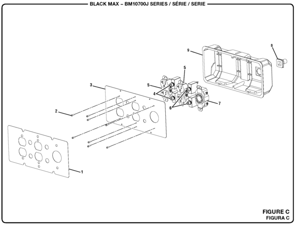
Figure 1-Typical CS Generator. CS is very similar. INTRODUCTION.
The CS and CS generators . A basic wiring diagram is shown in.
Delco Remy type CS and CS series alternator service bulletin. complete circuit, reference must be made to the vehicle manufacturer’s wiring diagrams.Sep 08, · CS alternator wiring, is sense wire needed?

Discussion in ‘Electrical the F is disconnected and of course I have a heavy gauge wire going from the post to the battery any help would be greatly appreciated (4 pins, 2, 3 or 4 wires come out of it) then that is a CS/ alternator. wentworth, Sep 8, wentworth, Sep. Minecraft Circle Diagram.
Standing Rigging Diagram. 3 Position Switch Wiring Diagram.
Ocean Ecosystem Food Chain Diagram. Plano Concave Lens Ray Diagram.
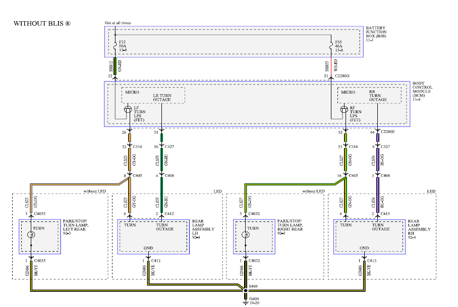
Chevrolet C Wiring Diagram. Fantastic Fan Wiring Diagram. Simple Boat Wiring Diagram.
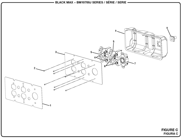
Browning Buckmark Parts Diagram. Giant Octopus Diagram.
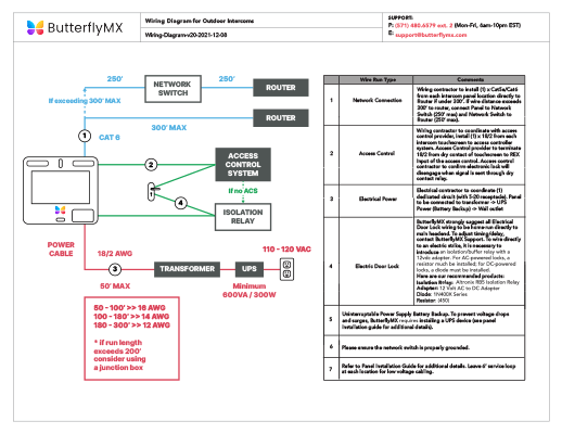
Dodge Durango Wiring Diagram. 6 TOOLS NEEDED In addition to your regular tools, you will need, at least, the following tools: Crimping Tool Note: Use a quality tool to avoid over-crimping. Wire Stripper Test Light or Volt Meter.
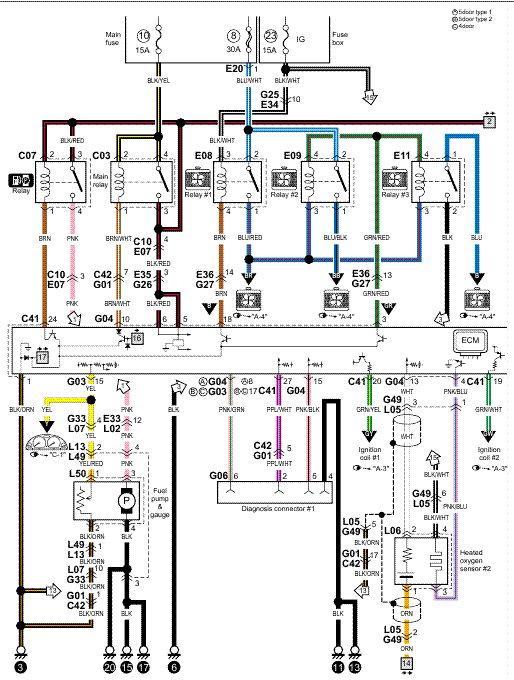
GM CS Series Internal Regulated Alternator Wiring. Wiring instructions for the GM Delco Remy internally regulated CS alternator.
The GM Delco-Remy cs alternator was used on GM vehicles from about was a transitional period for the cs The “F” terminal is connected internally to field positive, and may be used as a fault indicator. The “S” terminal may be connected externally to a voltage, such as battery voltage, to sense the voltage to be controlled.
For complete circuit, reference must be made to the vehicle manufacturer’s wiring diagrams.How to Wire a GM Delco type CS series alternatorCsd Alternator Wiring Diagram – schematron.org