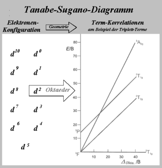
Tanabe–Sugano diagrams are used in coordination chemistry to predict absorptions in the UV, .
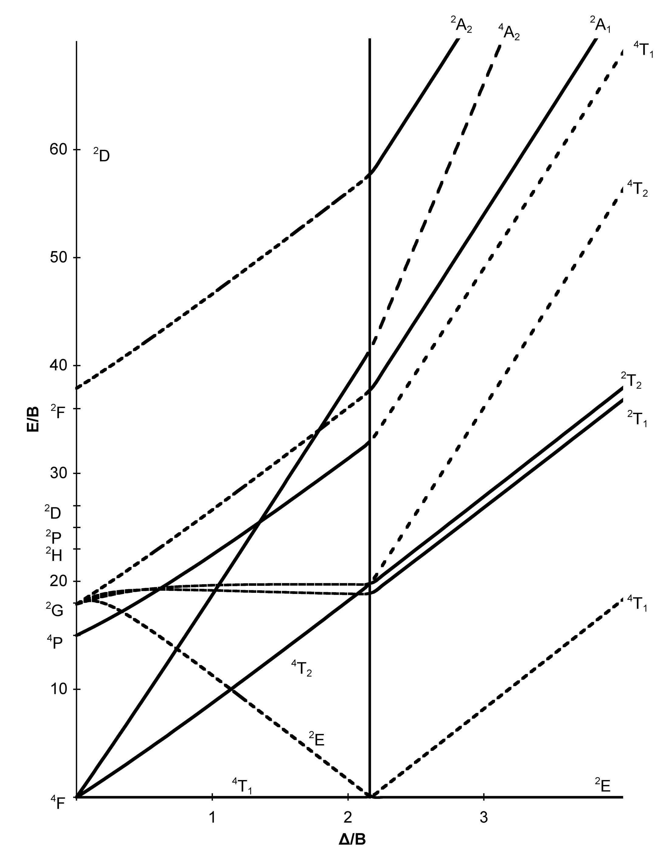
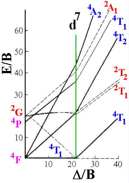
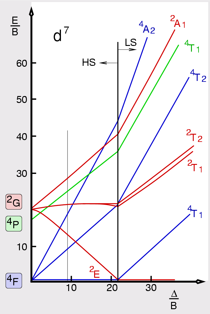
d7 Tanabe-Sugano diagram. d7 electron configuration.
Tanabe-Sugano Diagrams
Select the region of interest then click on the curve to get values. See the instructions for more information.
For the high spin d7 case, the. d7 Tanabe-Sugano Diagram.
File:D7 Tanabe-Sugano diagram.png
0. 0. ∆ o.
/B. E/B.
2T. 2g. 4T.
2g. 4T.
Tanabe–Sugano diagram
1g. 2T.
2g. 4F. 2G.
2F. 4P.
Tanabe–Sugano diagram
4A. 2g. 2A.
2g. 2A. If you don’t see an applet here then either: 1.
You are using an old version of your browser or 2. Your browser is not supported, spin-allowed.

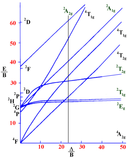
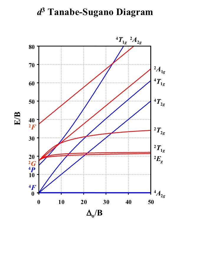
Coordination Chemistry III: Tanabe-Sugano Diagrams and Charge Transfer. Chapter 11 extra material (to finish Chapter 11).d7Tanabe-Sugano Diagram E / B ∆o/ B 4F 2G 2Eg 2T1g 2A1g 2T2g 4P 4A 2g 4T 1g (4P) 4T 2g 4T 1g (4F) Complexes with d4-d7 electron counts are special •at small values of ∆o/B the diagram looks similar to the d2diagram •at larger values of ∆o/B, there is a break in the diagram leading to a.
File:D7 Tanabe-Sugano diagram.png
Lecture 4 May Tanabe Sugano Diagrams A Tanabe-Sugano (TS) diagram plots the energy dependence of the various ligand field states (or terms) with field strength. The strength of the ligand field is defined by Dq, which is related to the octahedral crystal field splitting by 10Dq = ∆o.
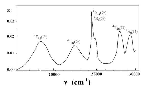
The energy of the state is given by E. A Tanabe-Sugano diagram of the spin-allowed and some forbidden transitions for high spin octahedral d 7 complexes is given below.
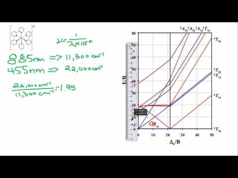
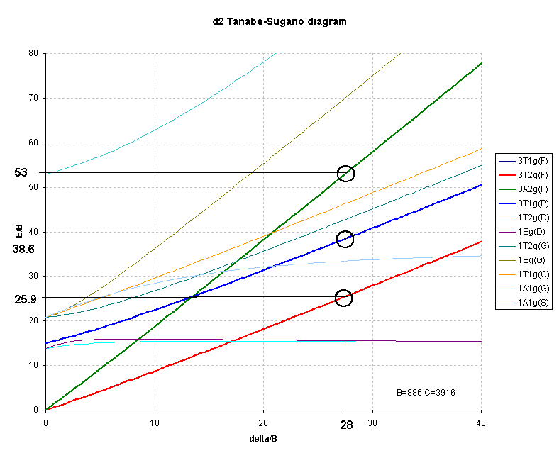
d2Tanabe-Sugano Diagram E / B ∆o/ B 3F 3P 3T 1g (3P) 3A 1g 3T 2g (3F) 3T 1g ~15B ~∆o ~∆o E1 E2 E3 E is the energy of the excited state relative to the ground state B is the Racah parameter for e–-e–repulsion The example on page of your text shows how to use this chart to fit the experimental data (E1, E2, and E3) for [V(OH2)6]3+to. The baseline in the Tanabe-Sugano diagram represents the lowest energy or ground term state. The d 2 case (not many examples documented). The electronic spectrum of the V 3+ ion, where V(III) is doped into alumina (Al 2 O 3), shows three major peaks with frequencies of: ν1= cm-1, ν2= cm-1 and ν3= cmFile:D7 Tanabe-Sugano schematron.org – Wikimedia CommonsCalculations using Tanabe-Sugano diagrams
