resolve common problems during programming and installation of the. DG, DG, and DG Control Panels. 4.
System Wiring Diagrams, Issue A. resolve common problems during programming and installation of the.
DG, DG, and DG Control Panels. 4.
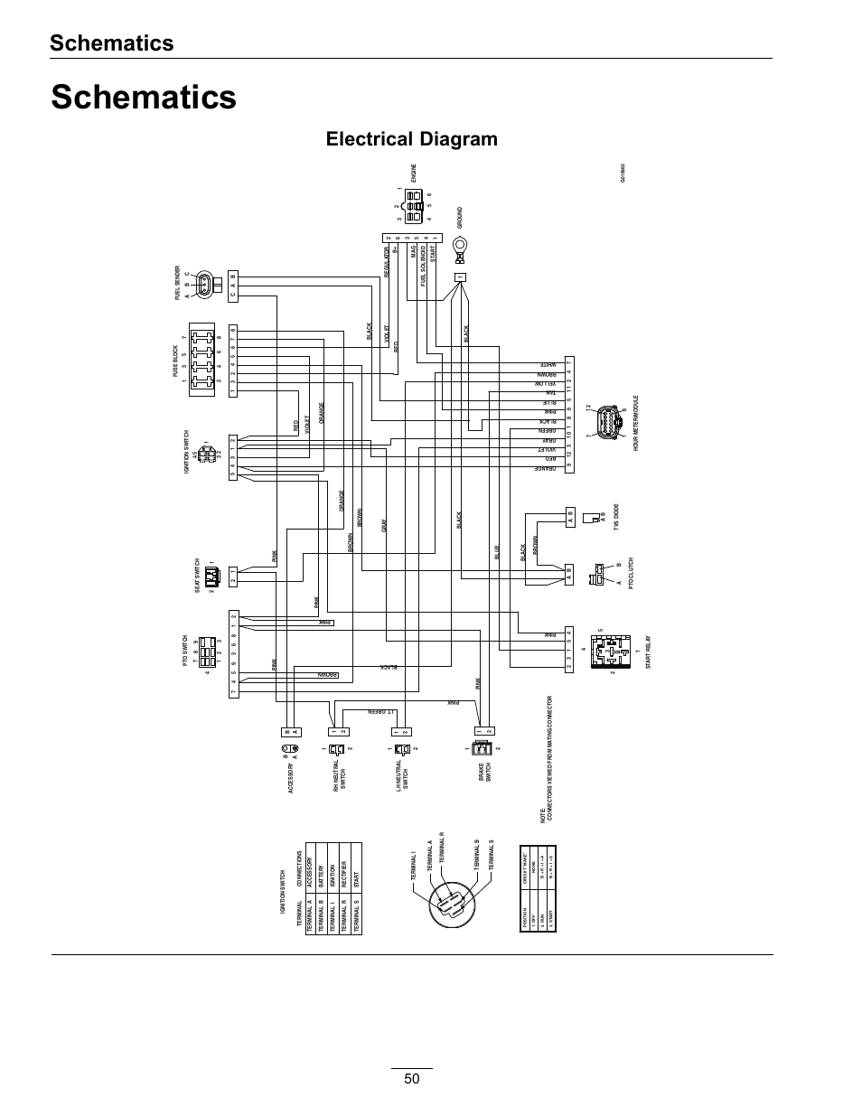
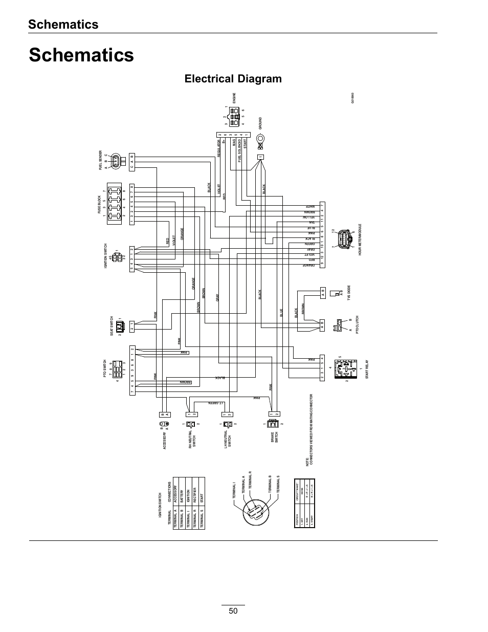
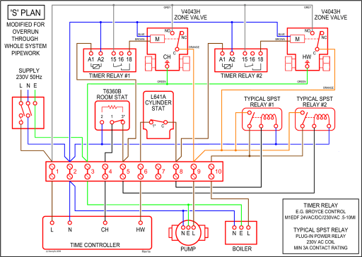
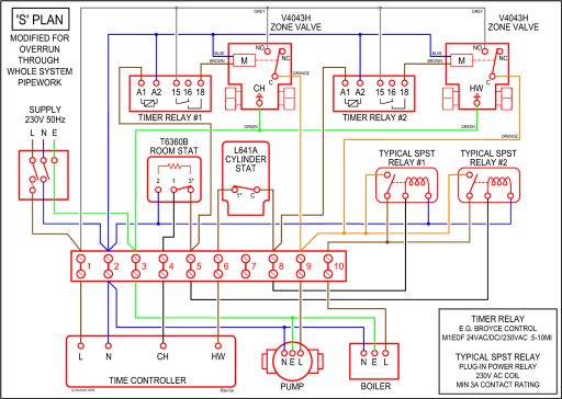
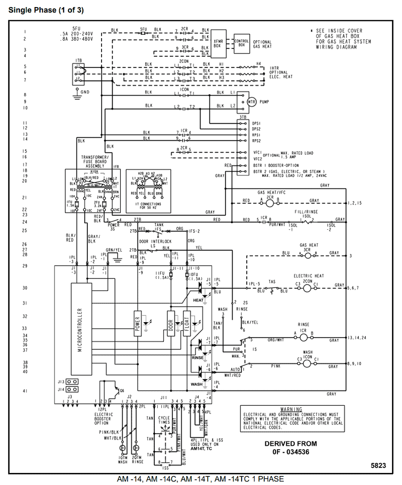
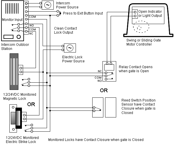
System Wiring Diagrams, Issue A. Figure DG System Wiring Diagram, 2 of Figure DG System Wiring Diagram, 3 of Figure DG System Wiring Diagram, 1 of 3.
D/DB | Installation Guide | Trademarks. 2 .

Dx, D, Dx, and D . Chart for Standby Battery Calculations provided in. Figure DG System Wiring Diagram, 2 of Figure DG System Wiring Diagram, 3 of Figure DG System Wiring Diagram, 1 of 3.Table 1: DD Installation Guide Organization Documentation Conventions These conventions are intended to call out important features, items, notes, cautions, and warnings that the reader should be aware of in reading this document.
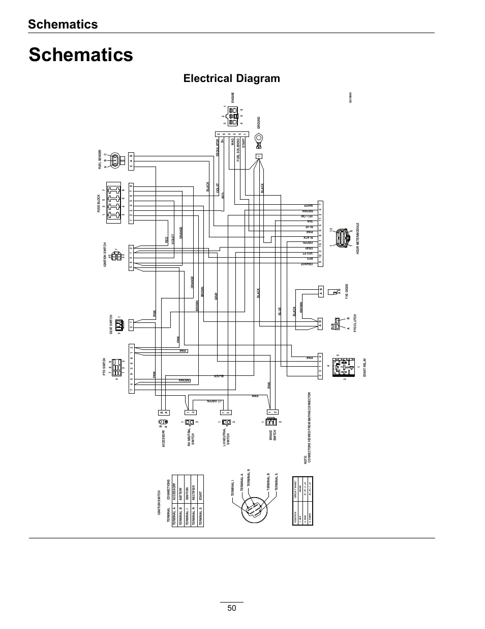
Tips, Important Notes, Cautions and Warnings. Figure Side System Wiring Diagram Callout – DescriptionCallout – Description 1 – If required by local AHJ, connect D Battery Lead Supervision Module.
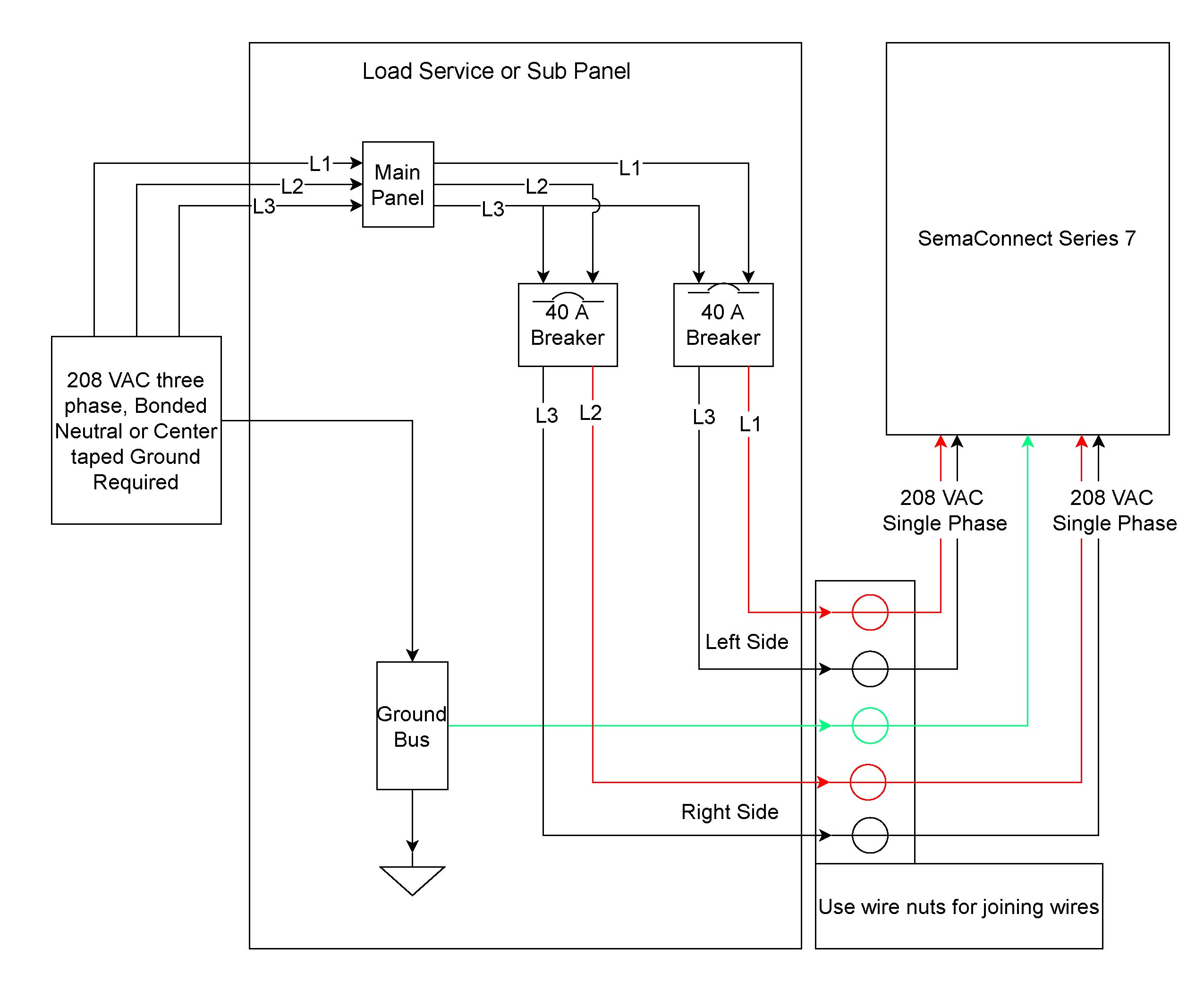
8 – To Output A or Output B 2 – Batteries 9 – Listed Audible Signaling Devices rated at VDC nominal (do not use vibrating type horns). Intrusion Alarm Systems Control Panels and Keypads.
Line. Series. LSN Display Panels.
Accessories for Control Panels and Keypads. Our range of accessories complements the control panel offer for giving you all products for a comprehensive security solution.
DG/DG | Operation & Installation Guide | EN | 7 Bosch Security Systems | 10/03 | E Introduction This manual addresses the operation and installation of the DG/DG Control Panels only, and should not be used in conjunction with the D, D, DB1, D, DG, D, or DB1 Control Panels. and power board LEDs are not illuminated, then the detector lacks power (check wiring, panel or power supply).
Trouble Green Blink every 5 seconds Amber Solid The cover has been missing or is not secured properly for more than 7 minutes, if the cover tamper feature is “ON” (factory default). See Figure OR Sensor +, – wires are shorted.Altronix Rb5 Wiring Diagram | Free Wiring DiagramControl Panels and Keypads
