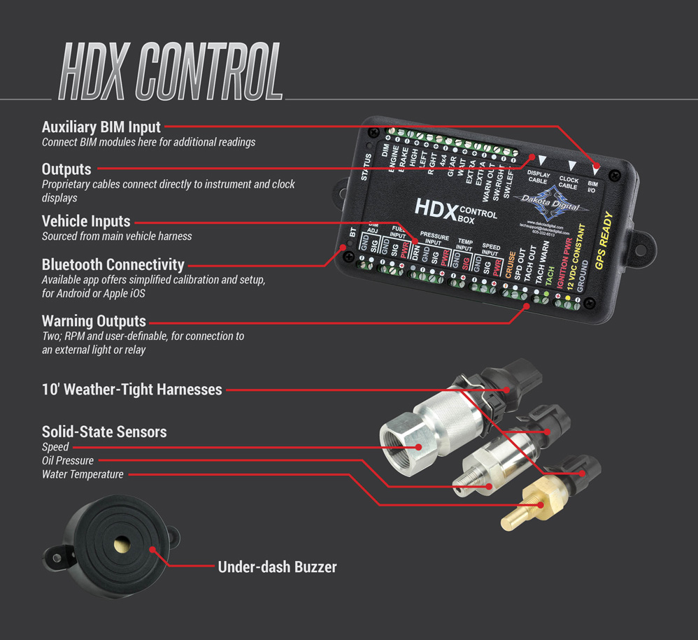
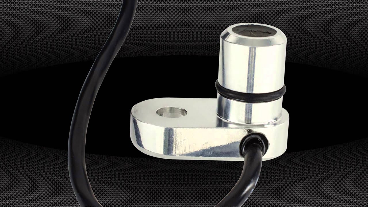
So we decided to ditch the 7-pound hunk of steel and aluminum for a slick, compact digital speedometer from Dakota Digital.
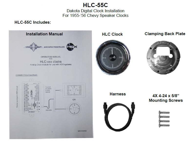
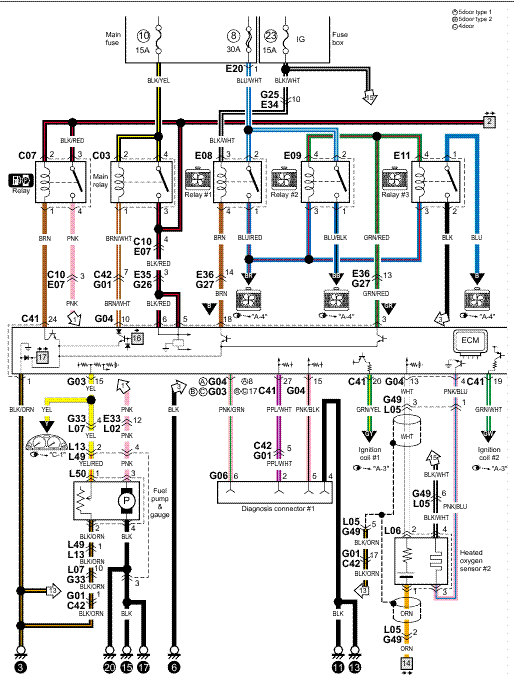
Examining the wiring diagram from service manual and reading the instructions for the Dakota (Model MCL for – ) speedo/tach. SPEEDOMETER/TACHOMETER INFORMATION GAUGE. Please read this before beginning installation or wiring.
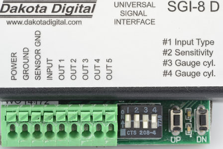
FUNCTION SWITCH. The switch on the left of.
I took apart the Suzuki cluster to inspect it and better understand the wiring and light Modified Schematic with the installation of the Dakota Digital MCV Examining the wiring diagram from service manual and reading the instructions for the Dakota (Model MCL for – ) speedo/tach.Dakota Digital MCL(-R Wiring Diagram. SPEEDOMETER SETUP Press and hold the switch while turning the key on and starting the engine.
Once the engine is running, release the switch. Sender Sender Pressure sender setup The gauge can use the following Dakota Digital pressure sensors: SEN ( psi), SEN ( psi), or SEN.
Jun 03, · wiring diagram for dakota digital speedometer. You search Auto repair manual PDF wiring diagram for dakota digital speedometer, if there are search results will appear schematron.org search results do not exist, please search by others keyword.
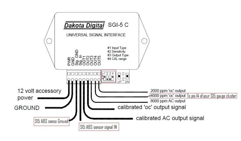
Jan 22, · Got the vss hooked up and it works great! Hooked Grey wire on the Dakota digital piece to the green wire (low signal) on the engine harness and the black wire on the Dakota digital piece to the purple (high signal) on the engine harness. And it no longer stalls/dies when letting off the throttle.
QUICK START GUIDE DAKOTA DIGITAL VHX GAUGE SYSTEM This guide is designed to get you up and running quickly with the minimal amount of options installed. It shows a typical and abbreviated wiring diagram as well as how to set up your speedometer, tachometer, and fuel sensor.
Dakota Digital manufactures digital instrumentation and accessories for the automotive, motorcycle and car audio enthusiast.Speedo Wiring – Mini Speedo from Digital Help – Harley Davidson ForumsConsent Form | Hot Bike