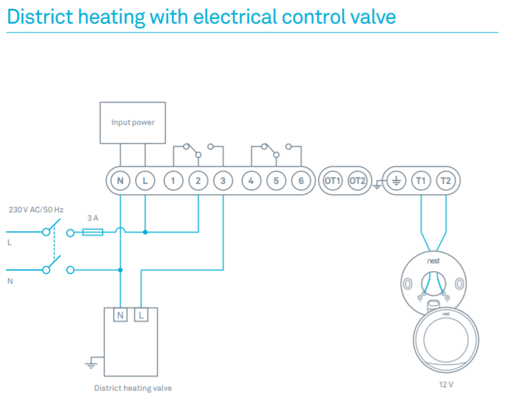
with vent dampers, the upgraded SU provides electronic control for nearly any intermittent .. gas control terminals as shown in wiring diagrams, using. The SU Universal Replacement Ignition Module is . SU Vent Damper Connector. .
ignition module; see the Electronic Ignition Service Manual. I’m replacing a Honeywell M with su.
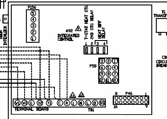
Trouble is, after I put in the new unit, I don’t get any spark at all. I see in the manual that for some. Ignition Sequence.
(After prepurge, if prepurge is selected). Integral.
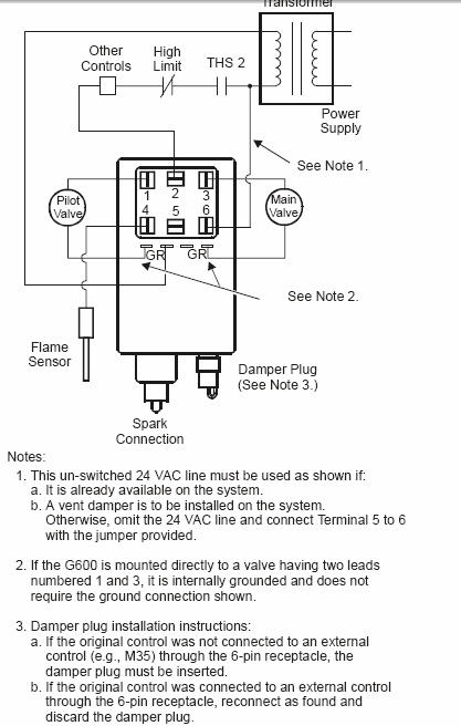
Damper. Connector a Use existing wiring harness to make connections to SU.

When replacing an existing ignition control with the SU, JUMPER. WIRE.

P1 VENT DAMPER. CONNECTOR.
Table 1. Typical Wiring Connections.SU Universal Intermittent Pilot Gas Ignition Control When replacing an existing ignition control with the SU, refer to for the correct DIP switch settings.
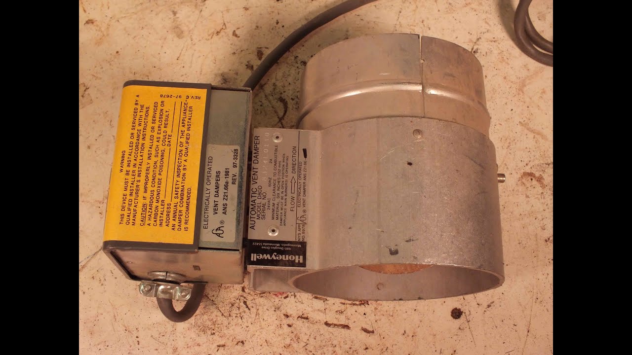
IMPORTANT Do not power the ignition control prior to setting the DIP switches. Check damper connection, damper wiring, and 24V connection on control.
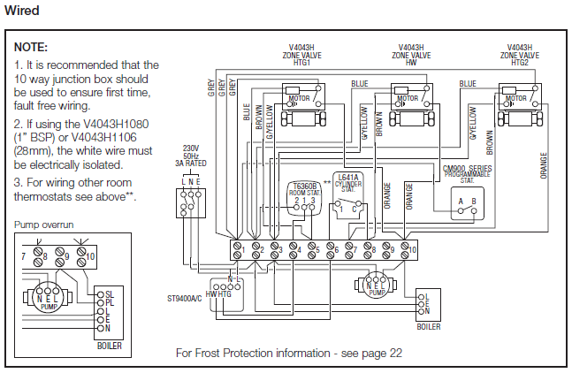
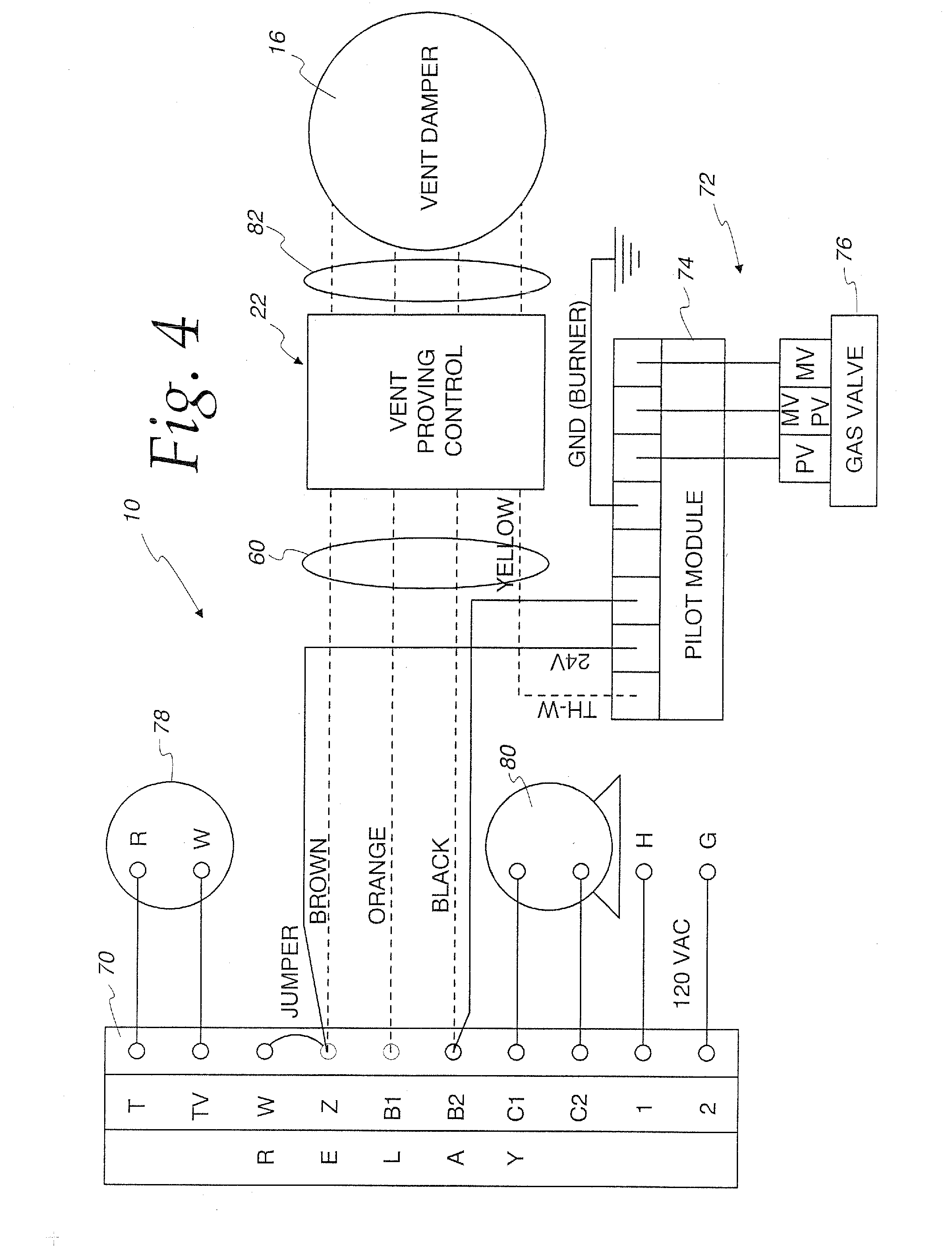
SU Universal Intermittent Pilot Module APPLICATION The SUPER TRADELINE® SU Universal Replace-ment Ignition Module is designed to provide easy field replacement of a wide range of intermittent pilot ignition modules manufactured by Honeywell, Robertshaw, Penn-Johnson and others. The SU module provides. if the vent damper is connected, wire 24v terminal, as shown.
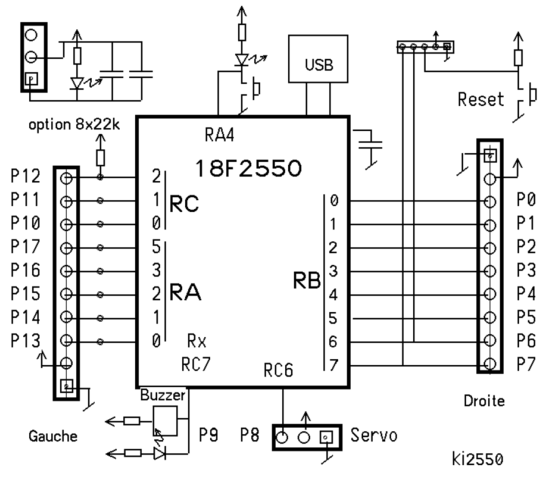
connect vent damper cable in place of plug shipped with the su. if no vent damper is connected, do not wire 24v terminal. page su universal interm ittent pilo t module start stage 1 trial for ignition stage 2 main burner operation fig.
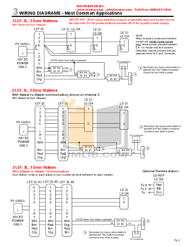
4. su in typical st application.
SU Universal Intermittent Pilot Gas Ignition Control SUPER TRADELINE® APPLICATION The SUPER TRADELINE® SU Universal Intermittent Pilot Gas Ignition Control Module is designed to provide easy field replacement of a wide range of intermittent pilot ignition modules manufactured by Honeywell, Robertshaw, Johnson Controls, and others. Wiring Diagram for Control Panels to SD Dampers and Airzone Systems Airzone System Wiring Diagrams SD Series Damper Wiring Diagrams Zone 1 PC X PO Zone 2 PC X PO Zone 3 PC x PO Term 1 Term 2 Term 3 Term 4 Airzone/ Flexdamper Terminals Robert Shaw SZC & SZD Control Panels NOTE: You only have to wire Terminal 1 (black wire) to the 1st Zone common.Installing Honeywell su – schematron.org Community ForumsHONEYWELL SU INSTALLATION INSTRUCTIONS MANUAL Pdf Download.
