Derating. 10 Electrical Installation Considerations. Safety Instructions.
Wiring Schematic. Contents.
VLT® AQUA Drive FC Wiring Configuration for an External Alarm Reset. Wiring Configuration for Speed Reference Using a Manual Potentiometer.
Wiring. EMC-compliant Installation.
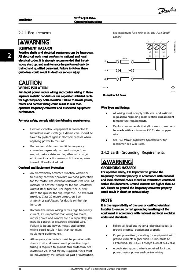
Grounding. Wiring Schematic.
Access. Motor Connection. AC Mains Connection.
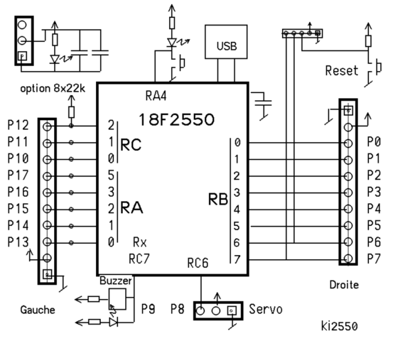
Illustration Basic Wiring Schematic Drawing. A = Analog, D = Terminal 37 is not included in FC (except enclosure size A1).
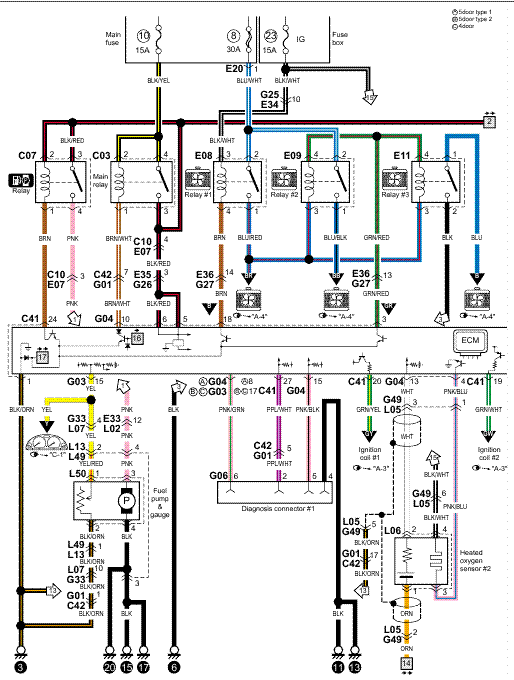
Relay 2 and terminal VLT. ®.
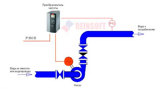
AQUA Drive FC kW schematron.org Purpose of the Manual. 6 .. Illustration Frequency Converter Block Diagram.
Area.Extended Options Cabinets If a frequency converter is ordered with one of the following options, it is supplied with an options cabinet that makes it taller. communications wiring, and control terminal functions.
3 Start Up and Functional Testing provides detailed procedures for start up, basic operational programming. Our technical documentation database contains the most up-to-date PDF versions of all manuals, design and programming guides and operating instructions.
You can search for documentation for both VACON® and VLT® brands. Cascade Controller Wiring Diagram Fixed Variable Speed Pump Wiring Diagram Lead Pump Alternation Wiring Diagram 5 Special Conditions Manual Derating Derating for Long Motor Cables or Cables with Larger Cross-Section Derating for Ambient Temperature 6 Typecode and Selection Contents. Line Power Wiring Overview Motor Wiring Overview DC Bus Connection Brake Connection Option VLTp is a registered Danfoss trademark.

11 Index VLTp AQUA Drive Instruction Manual Contents Protective grounding of the VLT AQUA Drive FC and the use of RCDs must always follow national and local regulations.VLT® Refrigeration Drive FC | DanfossDanfoss VLT AQUA Drive FC Manuals