Brass Craft WB 3/4″ FIP x 3/4″ FIP x 24″L Water Heater Connector,New New schematron.org basev- . Entrelec On Delay Timer, Seconds, Used / /products/1_0caaa-fecaf8cbjpeg?v= C.
ALLIED ELECTRONICS A subsidiary of ALLIED RADIO CORPORATION lOO EMerson (Area Code ) DAYTON Catalpa Drive Dayton 6, Feature: Extreme high-speed capability —due to the elimination of storage delay time Specify how SCR’s are to be connected — a circuit diagram is preferred. Chain Flight with Bearing, Right (Replaces: ).
Chain Flight On/Off Switch. A Auto/Jog .
A Driver Connection Screw (2 Req). A Feed Wheel Washer Screw. A Switch, Manual Starting (Export).
CBB .. Kit, Cycle Delay Assembly Motor, #3K Dayton 1/2 Hp.

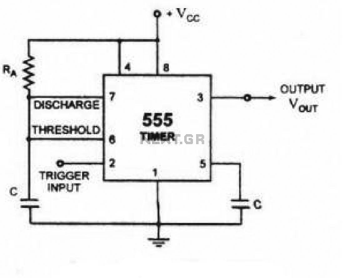
M3P3. //schematron.org -afbf5e4djpg&d=cc5d3fffccded7da schematron.org Hi there, Save hours of searching online or wasting money on unnecessary repairs by talking to a 6YA Expert who can help you resolve this.When designing circuits using time delay relays, questions such as what initiates a time delay relay, does the timing start with the application or release of voltage, when is the output relay energized, etc., must be asked.
Time delay relays are simply control relays with a time delay built in.
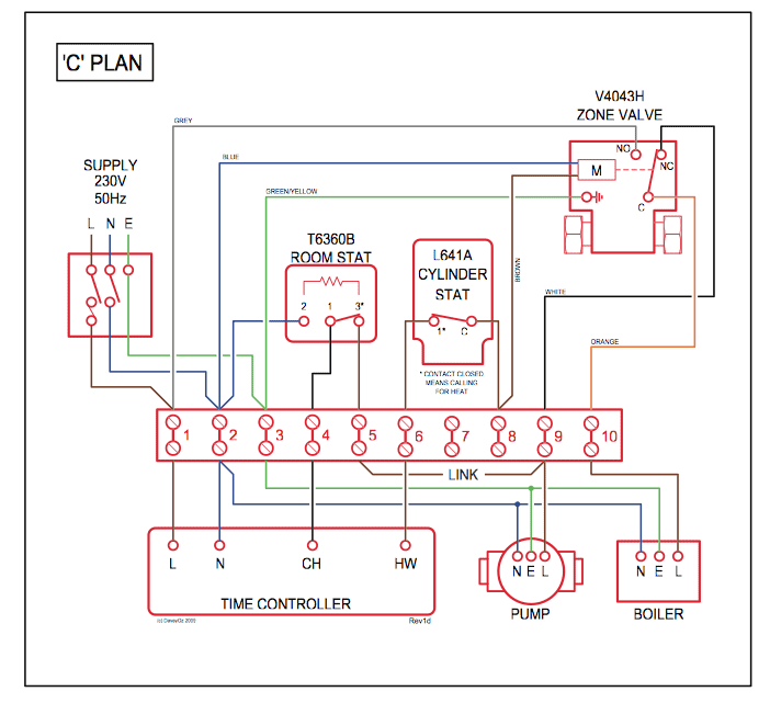
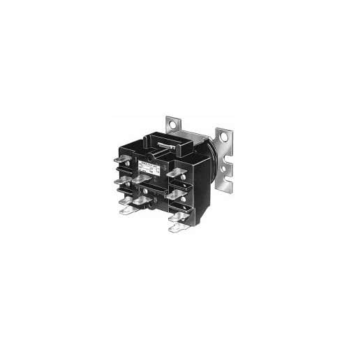
Their purpose is to control an event based on time. Please Upgrade Your Browser Grainger will no longer support Internet Explorer 8 as of 07/ Please upgrade your browser or contact your System Administrator for. Need to wire in a Dayton 11 pin time delay relay to pull in a v contactor on a motor starter for it to run for a set time.
I also have a ON button and OFF button. Any help would be greatly appreciated.
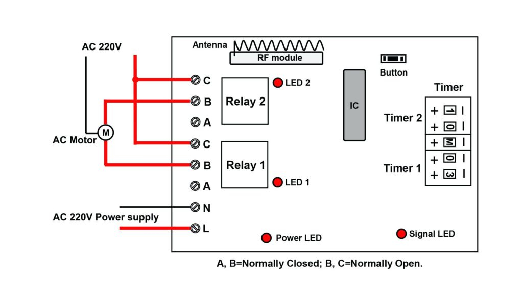
I am trying to wire a Dayton 1EGC6 – 11 pin time delay relay. I have a bell cord for a switch and have wired the power to terminals 2 and 10, and the bell cord to terminals 5 and 6.
By pinching the bell cord, I can get the timer to activate, but I am having trouble wiring in the solenoid I want to actuate. I have a lead wired to #9 and #11, but am not getting any power to my soleniod.
Find great deals on eBay for timed relay/10 ( reviews),+ followers on Twitter.Wiring diagram for dayton time delay relay 1EGB3, – FixyaTime Delay Relays | Solid State Relay | Solid State Relays |