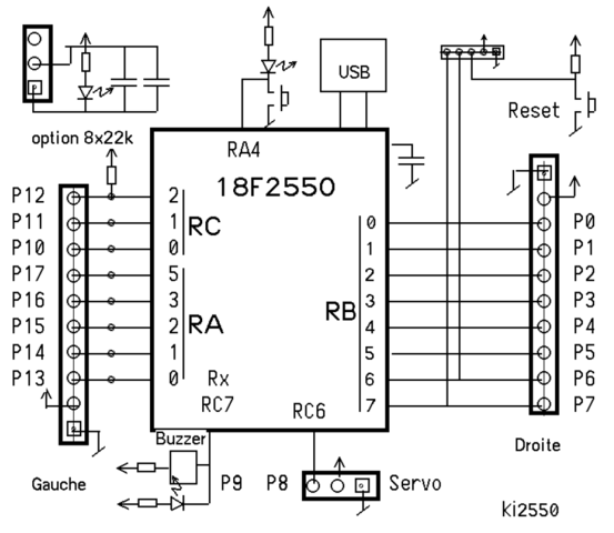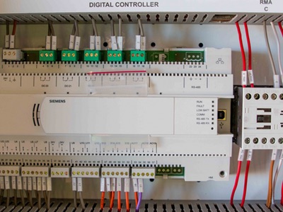
Wiring Diagram for BMS (DDC Panel) – Download as PDF File .pdf), Text File .
txt) or view presentation slides online. DDC panel.
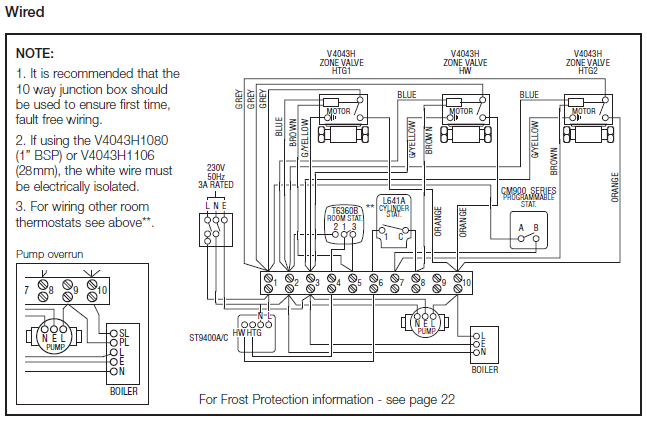
The CMA consists of field installable sensors for use with DDC control systems. Attach “CMA” label and wiring diagram to the inner control panel cover.
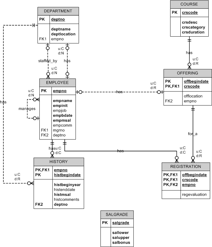
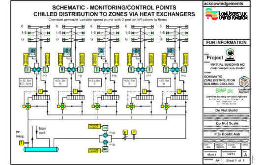
Provide the field devices and wiring including DDC controllers, relays, sensors, . Automatic Temperature Control (ATC) standards including control diagrams.
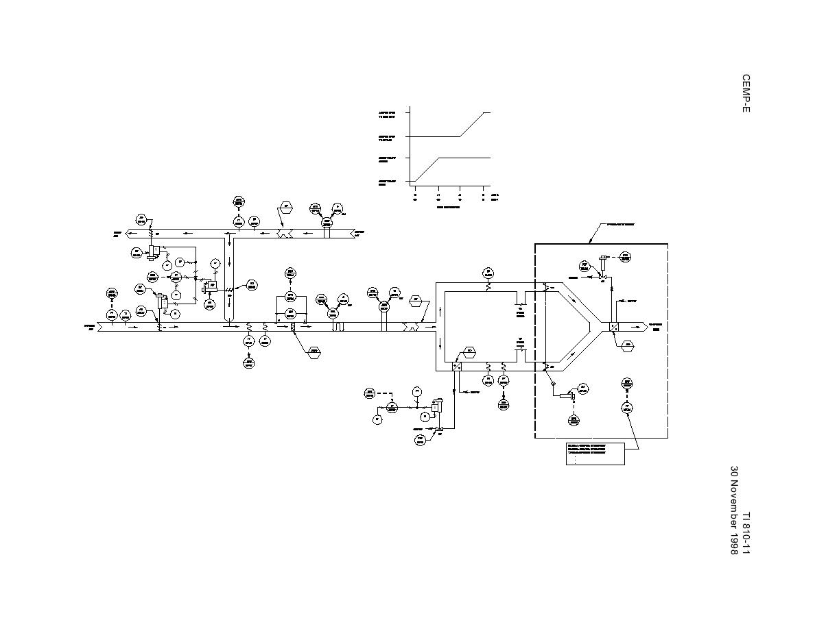
The RZ IP controller is a flexible and advanced IP based fully DDC Controllers. WEIGHT.
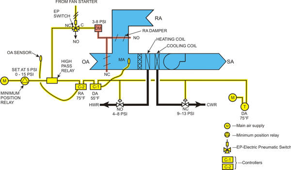
29 oz PROCESSOR BOARD WIRING DIAGRAM. Other Wiring.
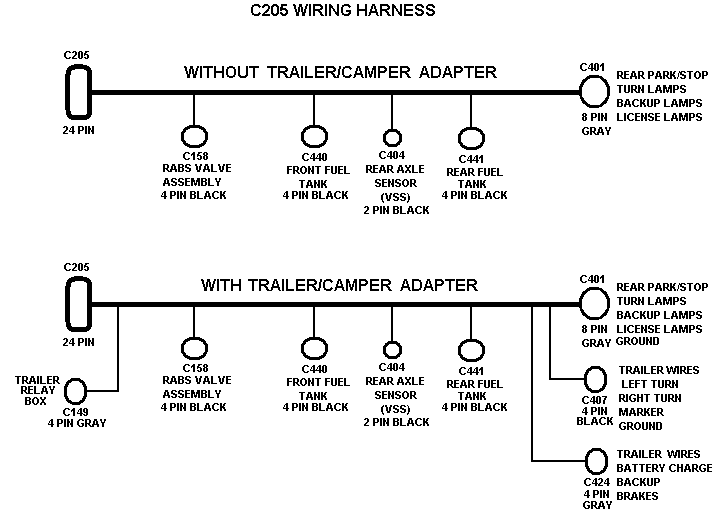
Wiring • Control Wiring – Multi strand, Annealed tin copper,with sheath and PVC BACNet Router SCHEMATIC DIAGRAM FOR BUILDING Sensors & DDC 2 core Twisted & Shielded Pair of Wire sq mm to sq mm 3.DCC wiring is different from DC blocks and cab control in consideration of wiring methods, but many of the same basic rules for electrical gaps etc. still apply.
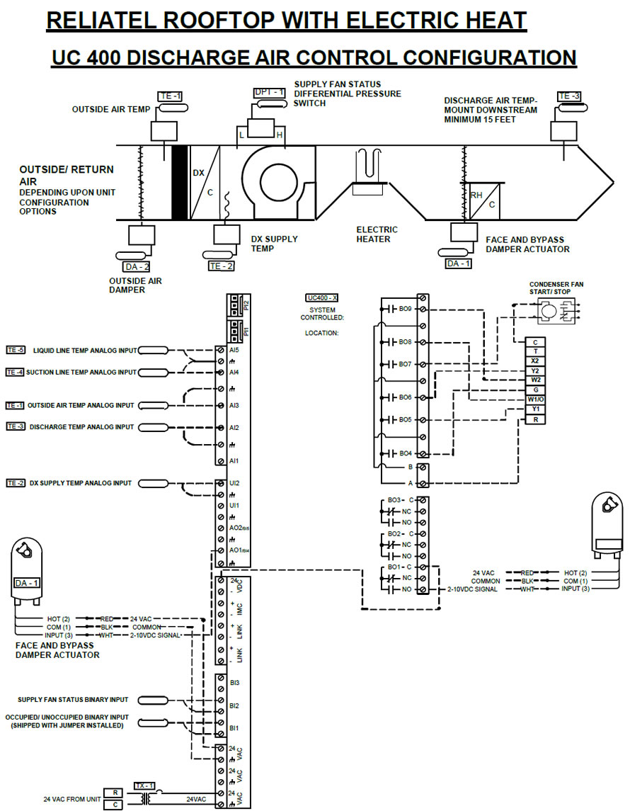
INSTALLATION, OPERATION, AND MAINTENANCE MANUAL AND DDC SYSTEM USER MANUAL FOR INDIRECT AND control sequences. Clearly mark all emergency shutoff devices. Table of Contents Copies of the wiring diagram, piping diagram and bill of material are in-.
Wiring for DCC isn’t as complicated as some would have you believe, but it is a very important component to the entire Digital Command Control Experience. BMS Automation wiring 1.
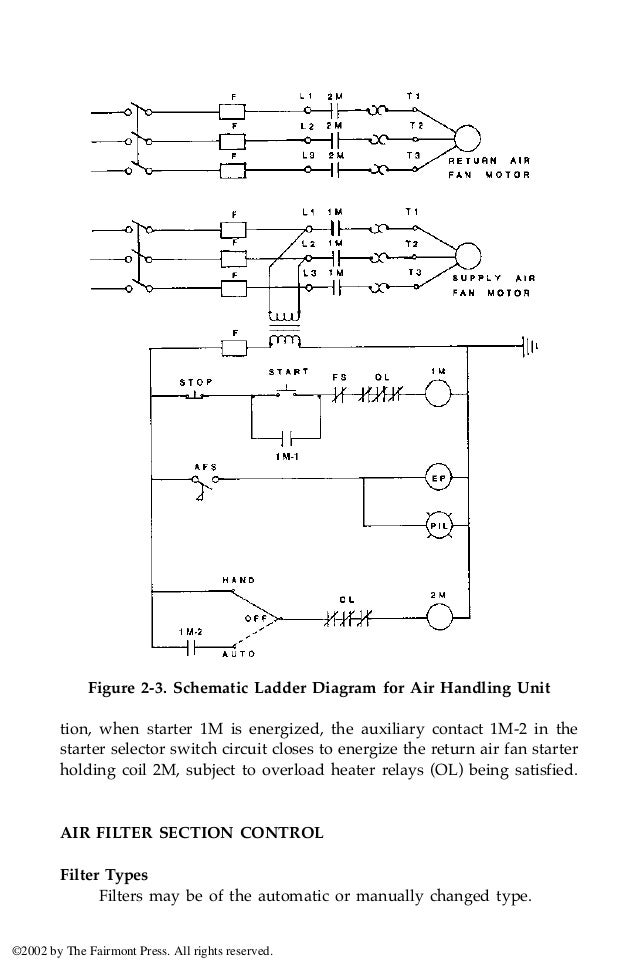
Wiring • Control Wiring – Multi strand, Annealed tin copper,with sheath and PVC insulation • Power Wiring – Multistrand Copper conductor with PVC insulation • Communication wiring – Multistrand, sheathed, stranded PVC insulated – CAT 5 or 6 Cable 2. DDC CONTROL LOOP 3.

according to the provided DDC wiring diagram. On units with ECM interface board cut provided terminals and connect wires on ECM control board as shown on Figure #9 Terminate DAT and LWT sensors according to DDC wiring diagram. Terminate DDC digital input 4 wires on Unit Protection Module (UPM) alarm contact by using the.schematron.org Article – DDC FOR HVAC SYSTEMSDCC Basics: Wiring a Layout for DCC Power
