The system also monitors several engine sensors that send electrical signals to the main ECM. Unlike DDEC I, the DDEC II ECM uses this information to actuate .
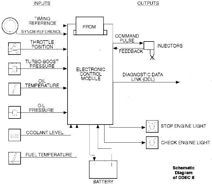
Figure Internal Engine Brake (Sheet ) ENGINE BRAKE FOR DDEC SYSTEM ECM The following wire schematics support the internal engine brake;. The replaceable PROM is an EPROM in the DDEC II ECM. The ECM has isolator mounts for both vibration and electrical isolation.
detroit wiring diagram
Depending upon application, some units Schematic Diagram of DDEC II. The DDEC II ECM is packaged in a . If ATEC is used, connect this wire to ATEC ECM. Wire Cut off black wire and insulate end. For Model DDEC II (2-mode), use the wiring diagram for.
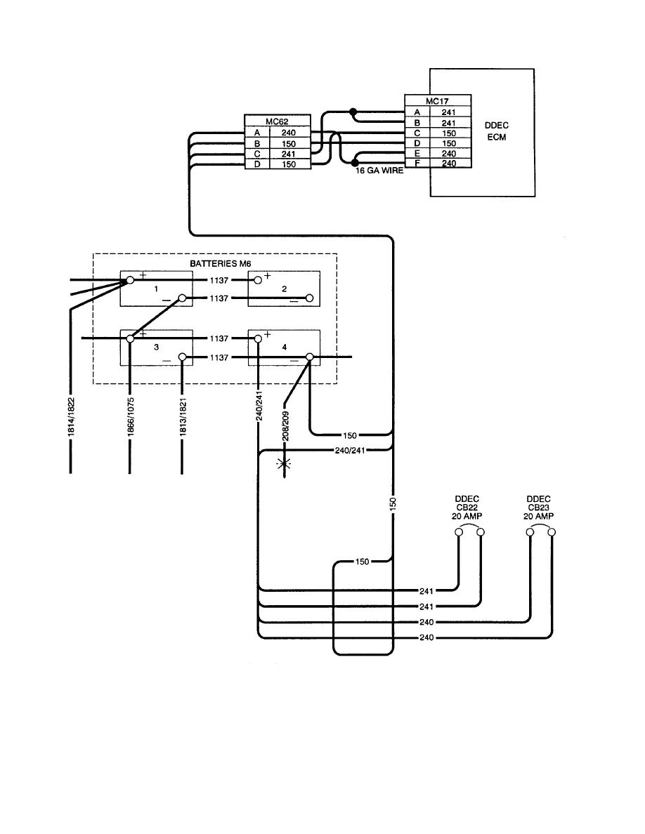
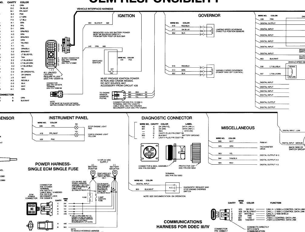
3 for partial (detailed) views of the full view of the DDEC II wiring diagram. See Fig.
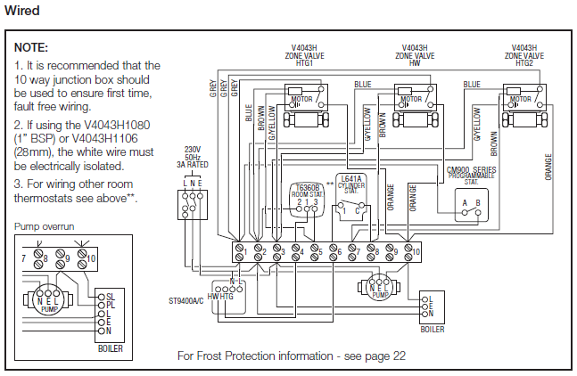
4 for a full . DDECIV+Multi-ECM+Troubleshooting+schematron.org Cargado por.Dec 02, · See Fig.1 for a full view of the Detroit Diesel Elec- tronic Controls (DDEC) II wiring diagram.
The ECM Lab – The Detroit Diesel Series 60 DDEC IV ECM
See Fig.2 and Fig.3 for partial (detailed) views of the full view of the DDEC II wiring diagram. See Fig.4 for a full view of the DDEC III wiring diagram (the engine side). See Fig.5 and Fig.6 for partial (detailed) views of the full view of the DDEC III wiring diagram.
Cummins Ecm Wiring diagram
Dec 23, · See Fig. 2 and Fig. 3 for partial (detailed) views of the full view of the DDEC II wiring diagram.
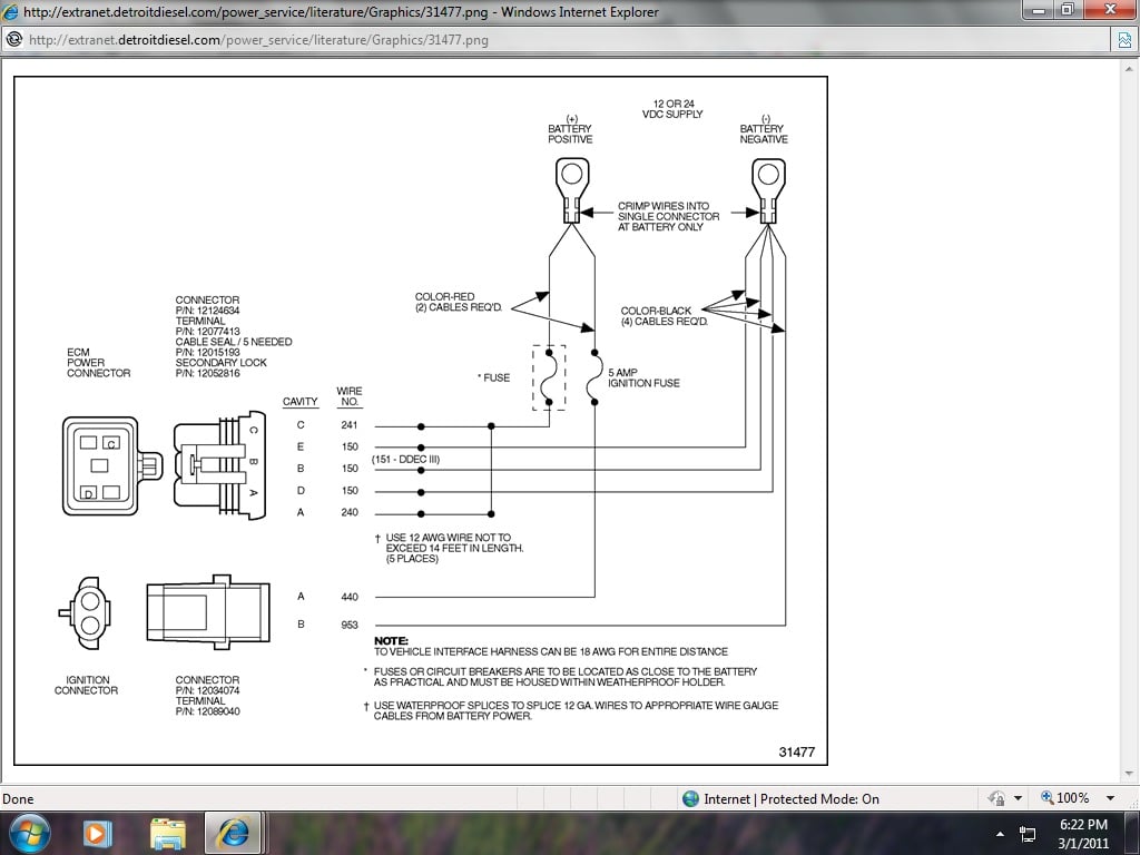
See Fig. 4 for a full view of the DDEC III wiring diagram (the engine side).
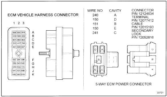
See Fig. 5 and Fig. 6 for partial (detailed) views of the full view of the DDEC III wiring diagram (the engine side)/5(11).
The replaceable PROM is an EPROM in the DDEC II ECM. The ECM has isolator mounts for both vibration and electrical isolation. Depending upon application, some units have fuel cooling of the ECM. The engine-mounted system simplifies vehicle wiring for greater reliability.
. HOME SERIES 50 DDEC II ECM SERIES 50 DDEC II ECM. The engine mounted system simplifies vehicle wiring for greater reliability.
The DDEC II ECM is a microprocessor. It is the control center of the DDEC II system.
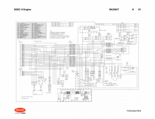
See Figure Schematic Diagram of DDEC II. The DDEC II ECM is packaged in a die-cast aluminum housing with sealed.
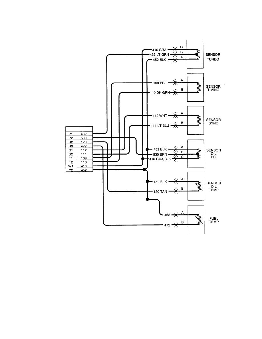
Specifically covered in this manual are troubleshooting and repair steps that apply to the DDEC II systems. The following is a list of topics contained in the DDEC II Troubleshooting M anual: SECTION 1.Schematic Diagram of DDEC II | Detroit Diesel Troubleshooting DiagramsDetroit DDEC II Troubleshooting Manual & Wiring | MyPowerManual
