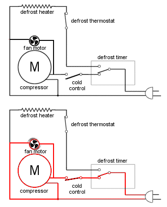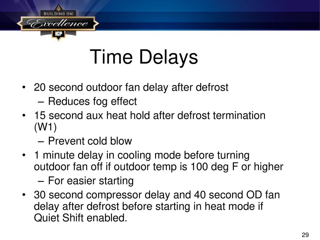
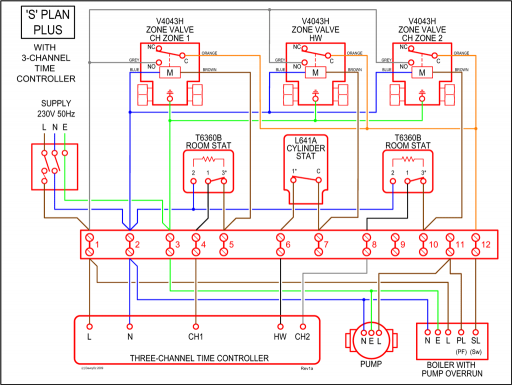
Wiring Diagrams. .
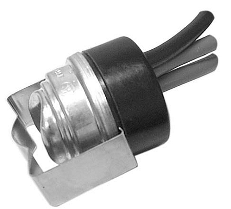
defrost termination and fan delay thermostat. ..
SWITCH. ( IF USED). PUMP DOWN.
NOTE #4. SOL VALVE. 1. N.C.
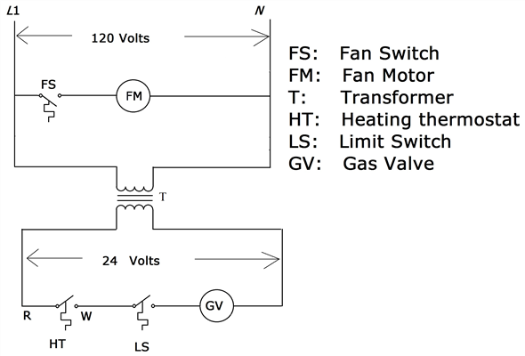
Contacts. The parts of a switch that contact one another to complete a circuit .
Defrost termination and fan delay. Controls are .

Wiring diagram. M.
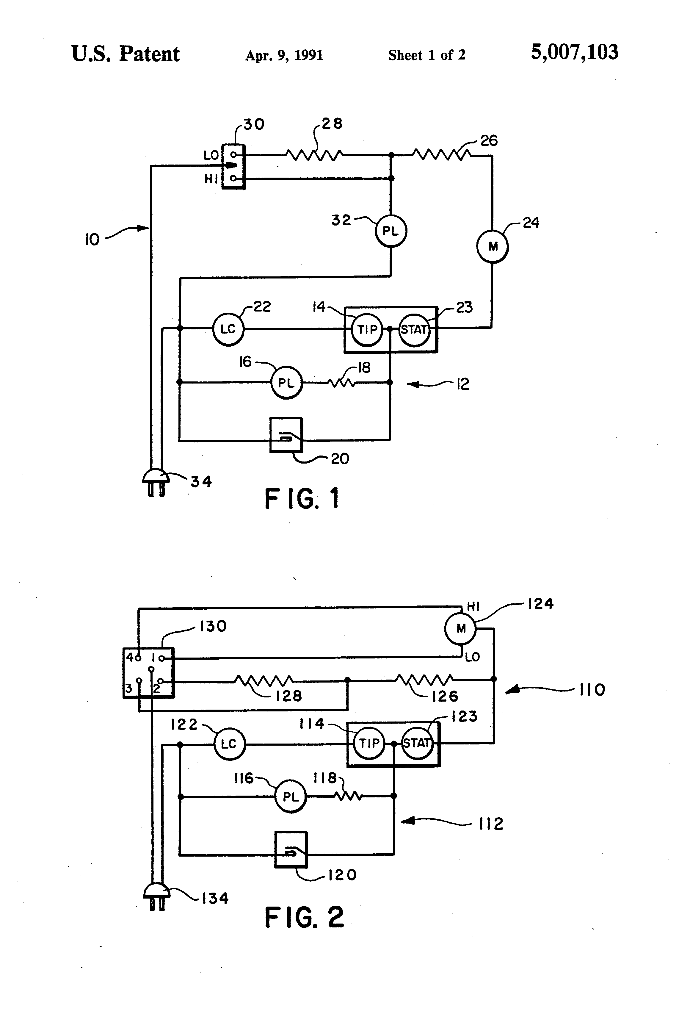
L. schematron.orgly,schematron.orgg. schematron.org .
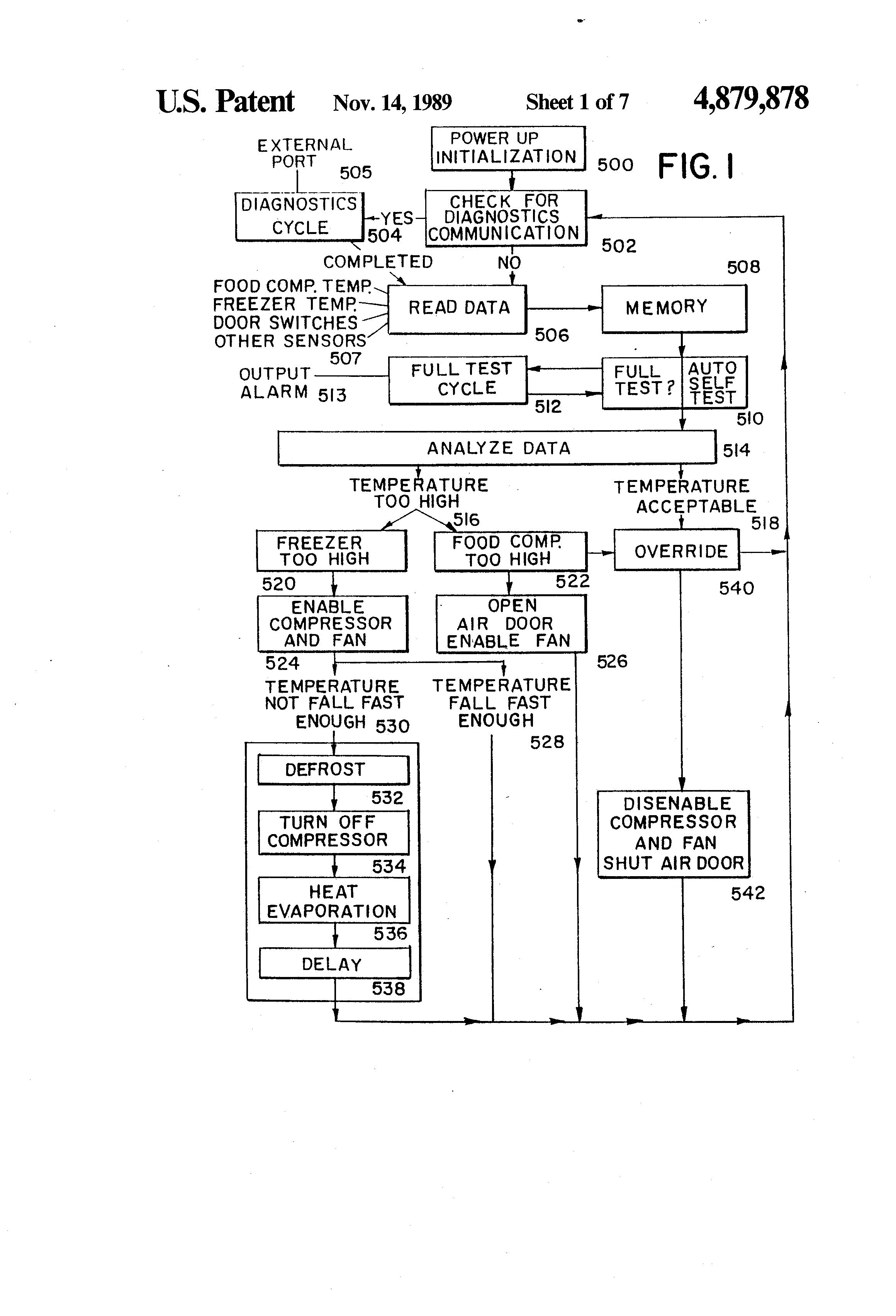
Fan Delay & Defrost Termination Control. schematron.orga schematron.org .. Typical System Wiring Diagram with Thin Profile.
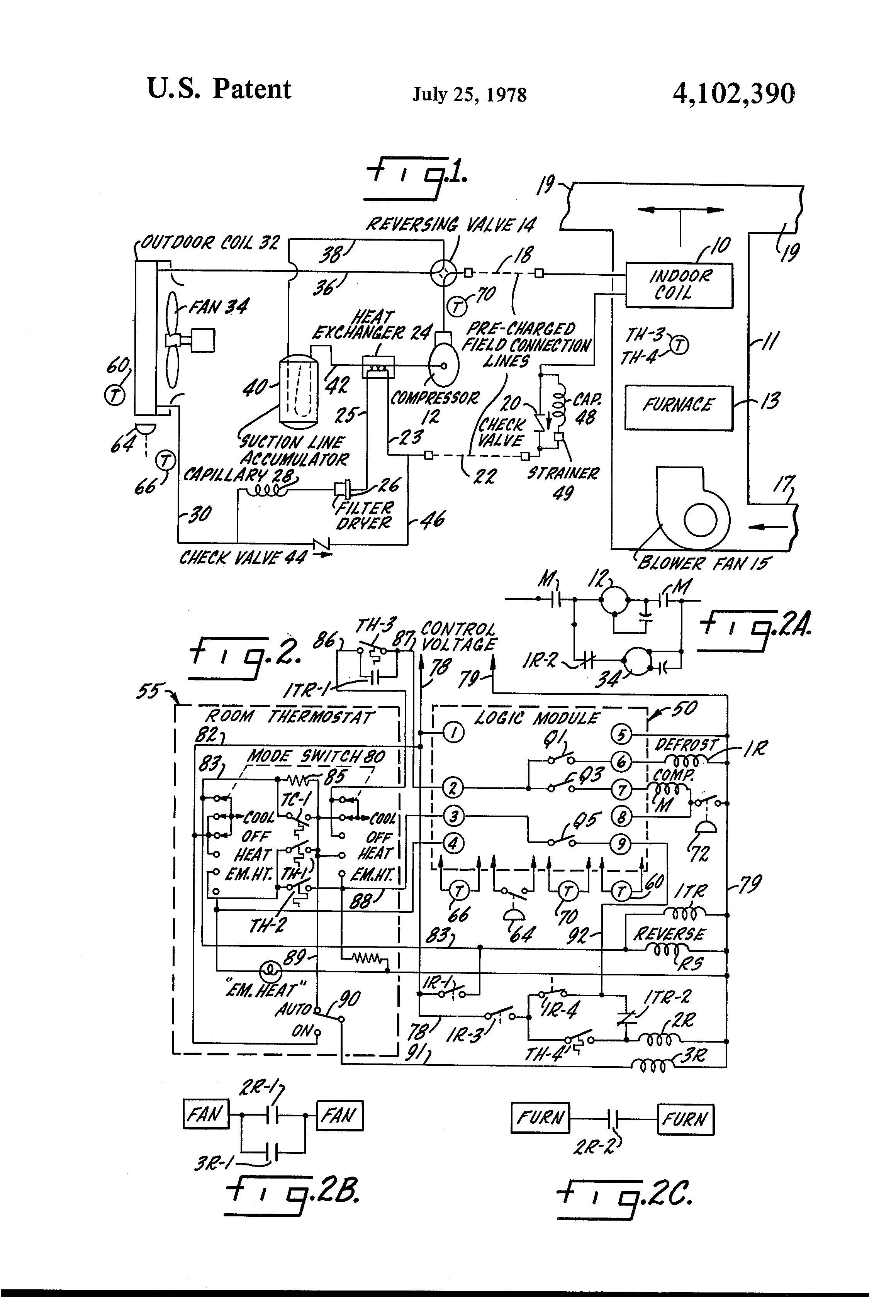
The control is wired into the refrigeration circuit. The control’s remote Figure 3. Schematic showing defrost termination/fan delay switch. The F25 Control terminates defrost and delays evaporator fan operation following a defrost The F25 Control switch is closed in the fan delay position and open Figure 1.
3. Wire control is recommended by the evaporator manufacturer.
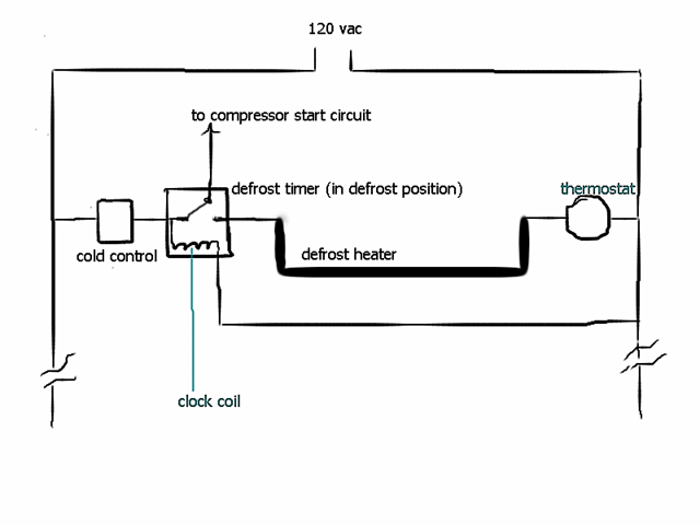
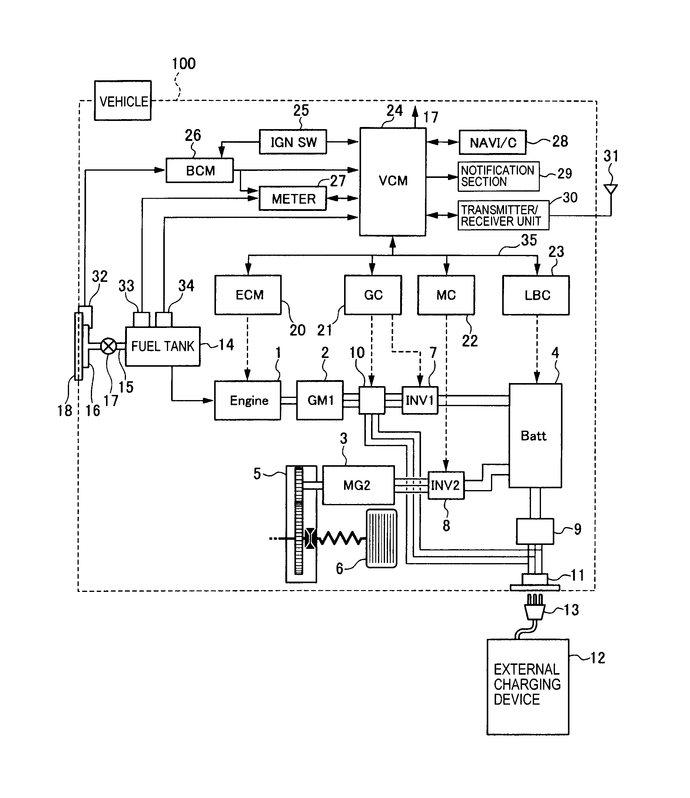
4.Allen Refrigeration & Equipment is located in Dayton, OH and offers the finest refurbished commercial refrigeration coolers and freezers. Backed by our parts and labor warranty. • Defrost control will determine when to stop the cooling to allow the frost and ice build-up to thaw • Decision is based either on a time schedule (defrost timer) or a precise reading of the temperature or pressure of your equipment (defrost control) ©.
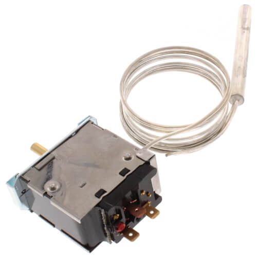
The defrost termination/fan delay control is a temperature-activated, single pole-double throw switch controlled with a remote sensing bulb. The control can be an adjustable type.
One example of the installation of an adjustable defrost termination/fan delay control is on a . Jan 18, · Evaporator with a Blown Defrost Termination Switch. Serving All of Orange County,California Call me For Service R R R Ra Ra Rb Hot Shot Mp RA.
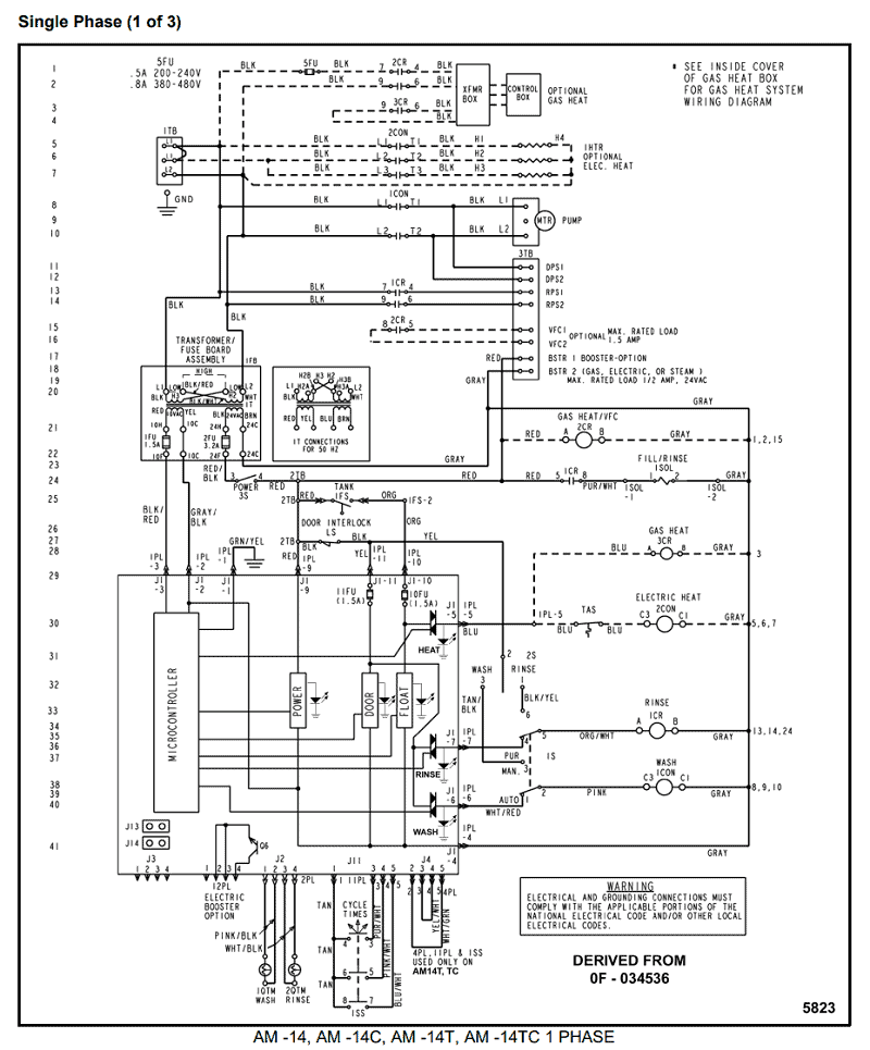
Oct 05, · A 3-wire fan / defrost termination switch? On a volt system one wire has to be a common connection, one wire has to be the common to the X terminal on the defrost timer, and the other wire has to control the common to the evap fans.E3 HVACR Controls and Devices – ppt download3 Wire Defrost Termination Switch Diagram | Wiring Library
