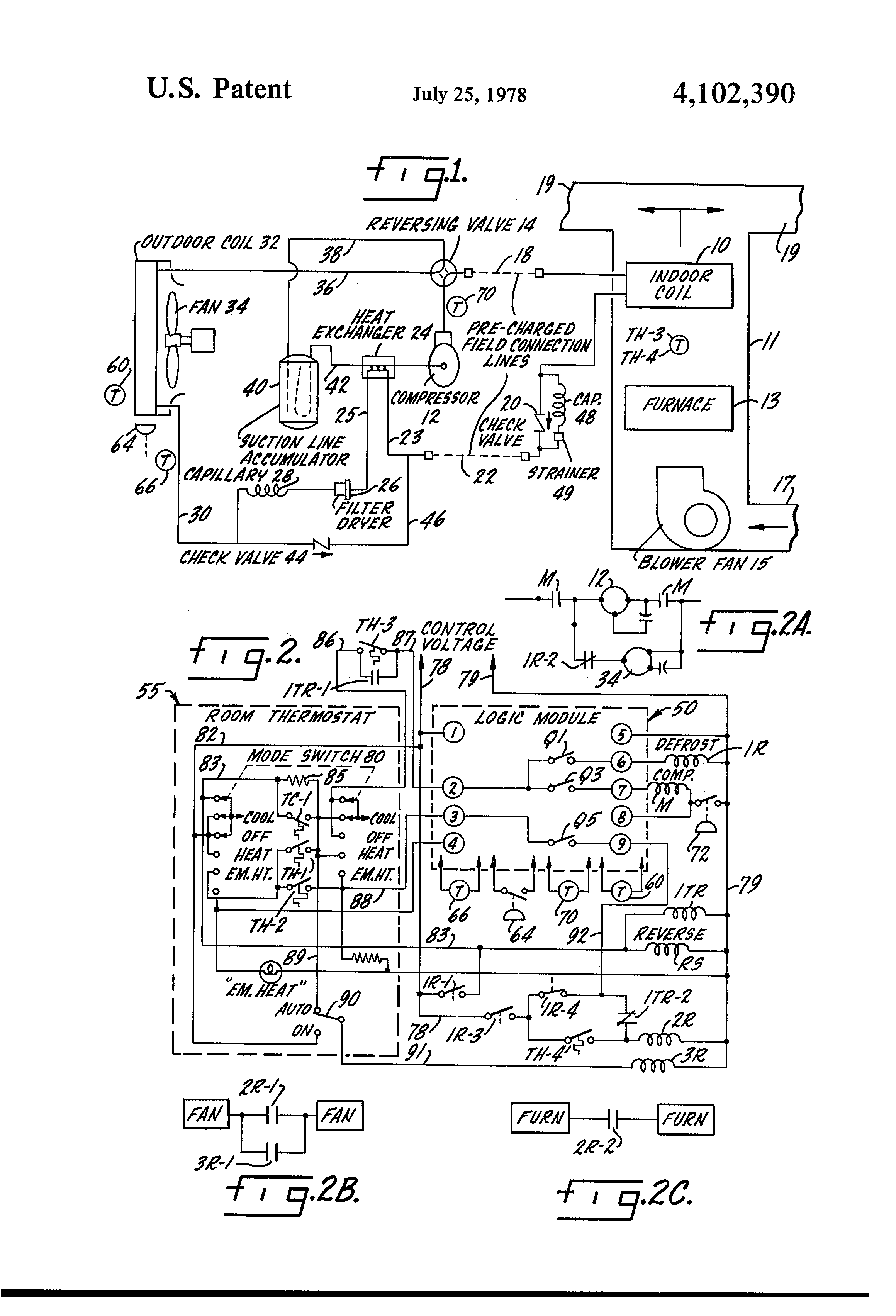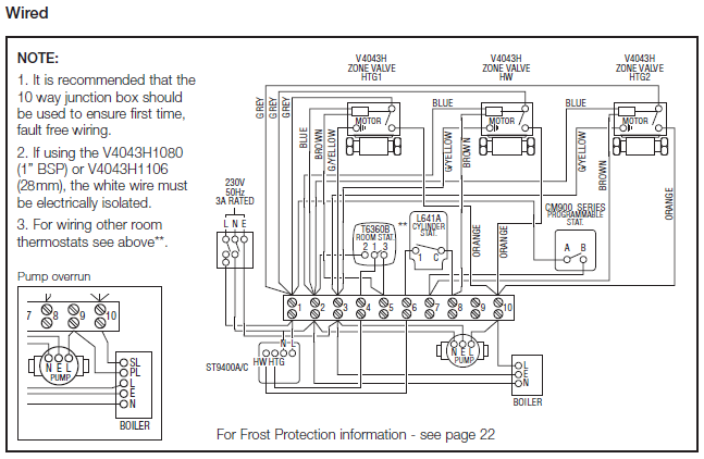
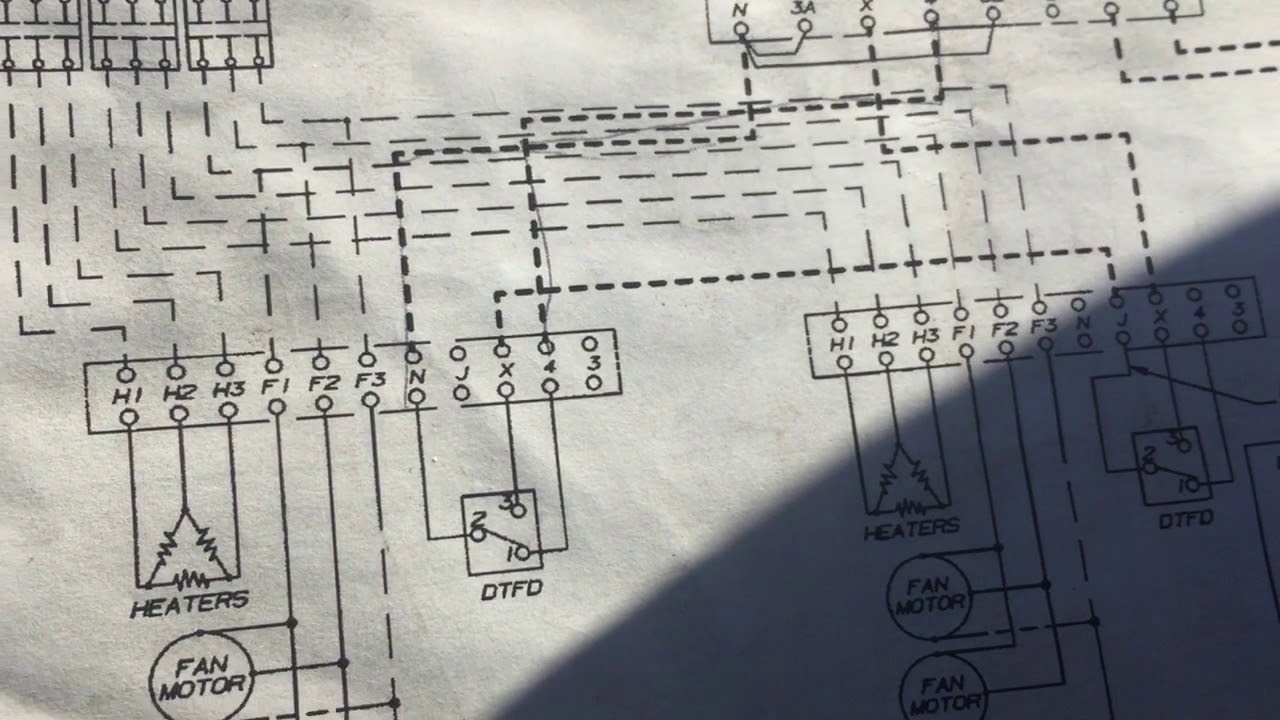
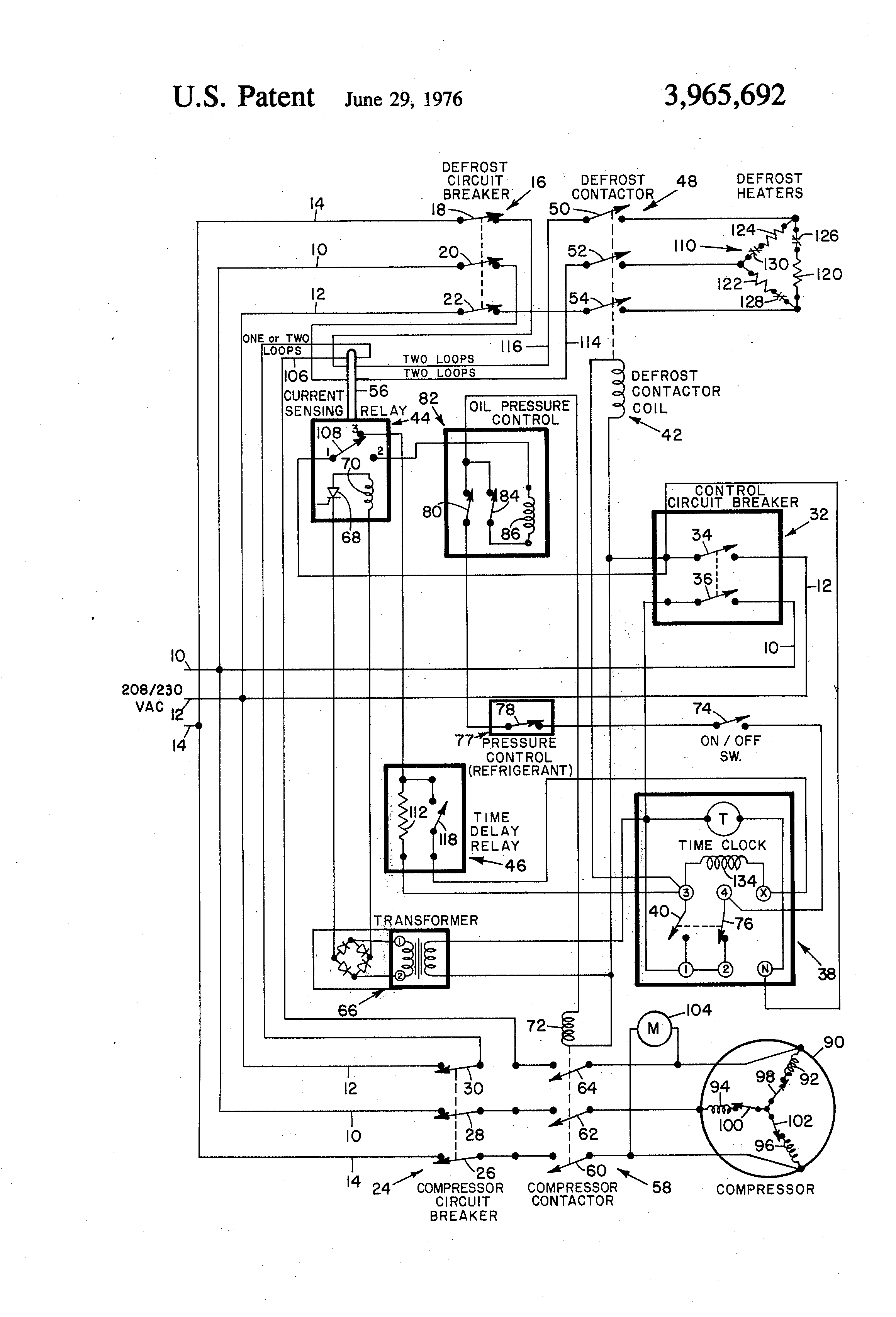
Wiring diagram for defrost termination switch defrost termination switch If its been working for years, the wiring is correct you just have to figure out, if its working. In a common wiring diagram for a time-initiated, temperature-terminated A temperature control is used as the defrost termination switch.
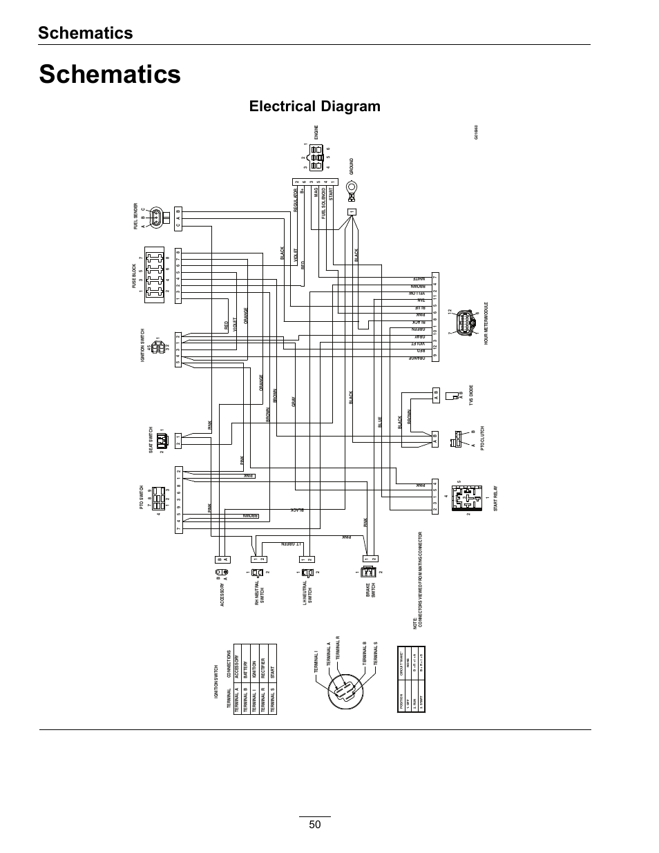
The “failsafe” setting is a backup to the defrost termination switch; If the defrost lasts too Wiring Diagram for W/I Freezer with Electric Defrost & Remote C.U.. 1.
Evaporator with a Blown Defrost Termination Switch. Serving All of Orange County,California Call me For Service If so, you may want to check into installing a defrost termination/fan delay control. Schematic showing defrost termination/fan delay switch.Home〉Diagram〉 Defrost Termination Switch Wiring Diagram 〉 Currently Reading Defrost Termination Switch Wiring Diagram Image Inspiring New Defrost Termination Switch Wiring Diagram.
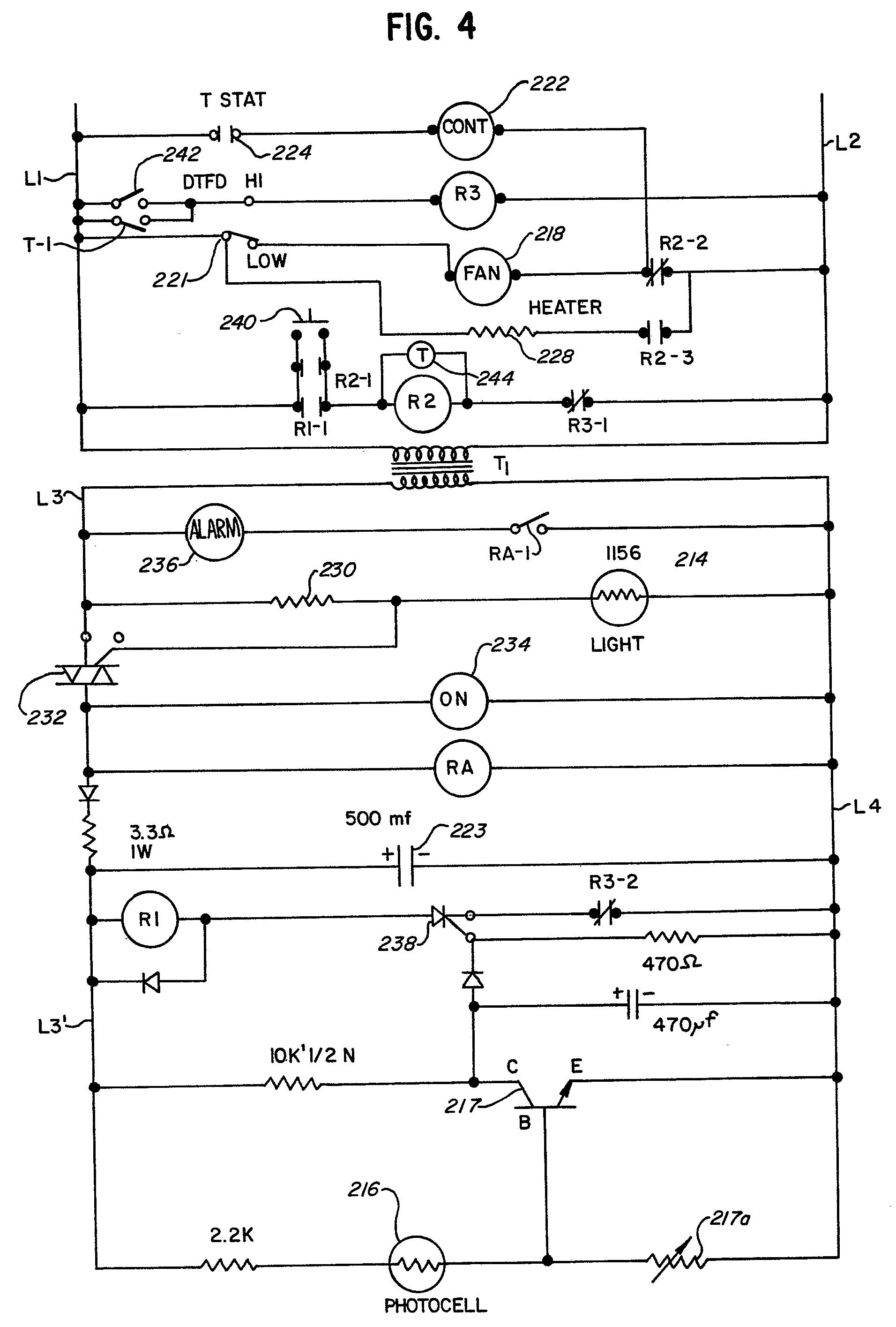
Jul 03, · most freezers have 2 controls. 1 is a defrost terminator and the other is a fan delay. the delay and the defrost terminator can sometimes be a.
Minecraft Circle Diagram. Standing Rigging Diagram.

3 Position Switch Wiring Diagram. Ocean Ecosystem Food Chain Diagram.
Plano Concave Lens Ray Diagram. Chevrolet C Wiring Diagram. Fantastic Fan Wiring Diagram.

Simple Boat Wiring Diagram. Browning Buckmark Parts Diagram. Giant Octopus Diagram.
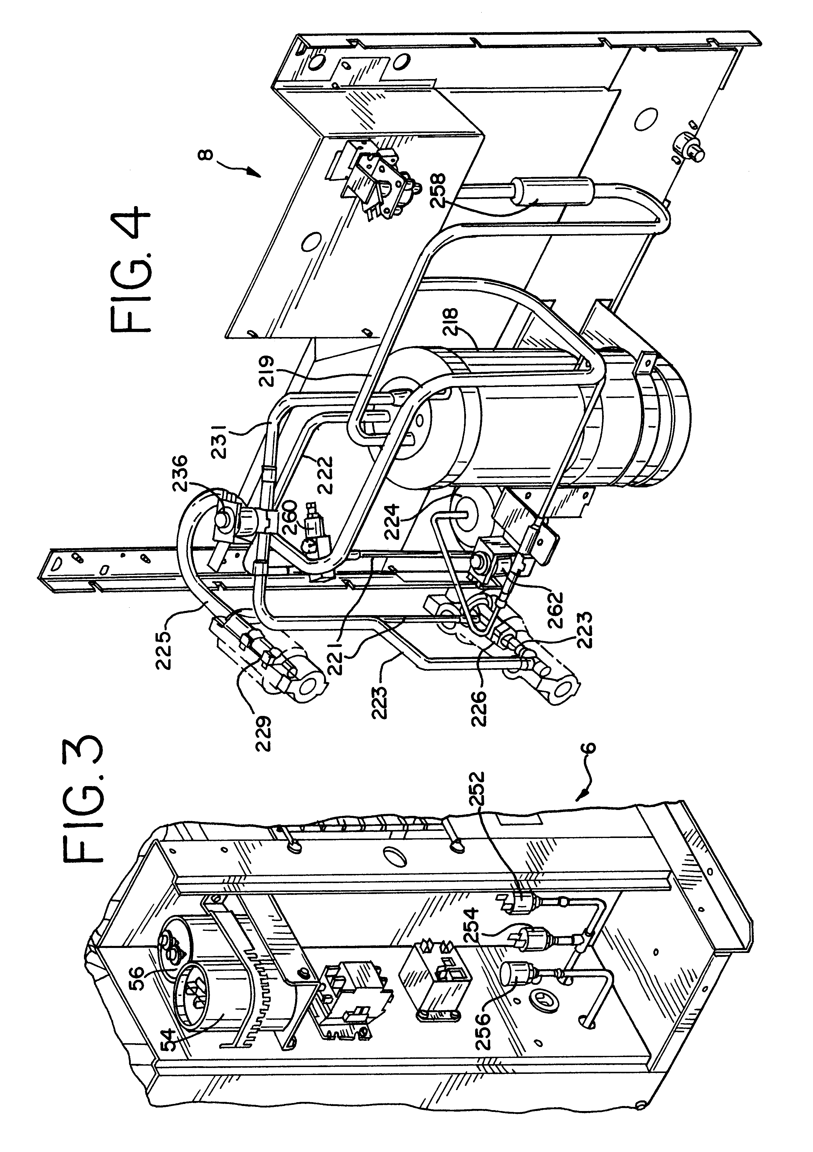
Dodge Durango Wiring Diagram. Jan 18, · Evaporator with a Blown Defrost Termination Switch.
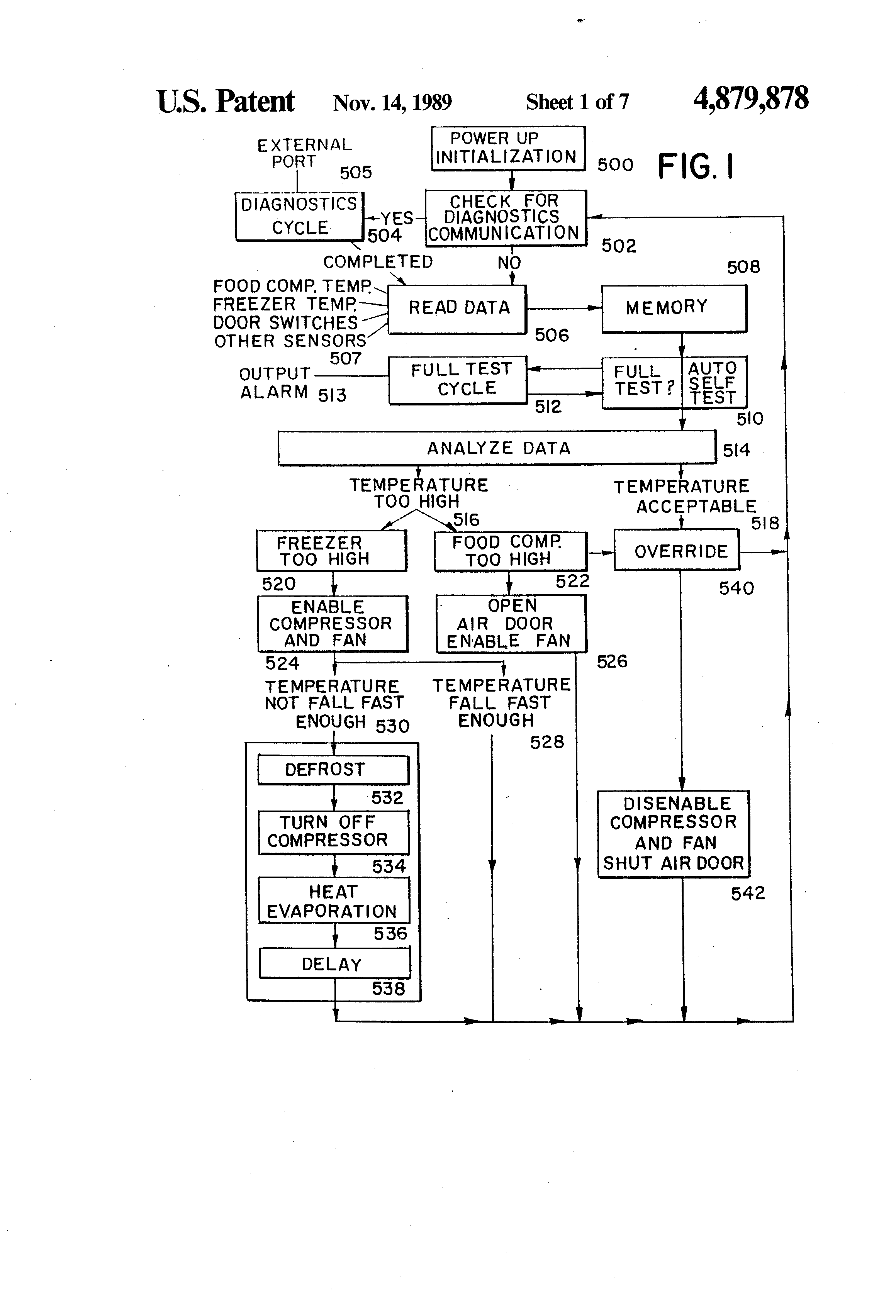
Serving All of Orange County,California Call me For Service R R R Ra Ra Rb Hot Shot Mp RA. Oct 05, · A 3-wire fan / defrost termination switch?
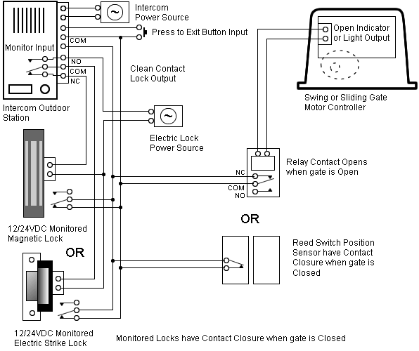
On a volt system one wire has to be a common connection, one wire has to be the common to the X terminal on the defrost timer, and the other wire has to control the common to the evap fans. The defrost termination/fan delay control is a temperature-activated, single pole-double throw switch controlled with a remote sensing bulb. The control can be an adjustable type. One example of the installation of an adjustable defrost termination/fan delay control is on a walk-in freezer’s evaporator.A 3-wire fan / defrost termination switch?3 Wire Defrost Termination Switch Diagram | Wiring Library
