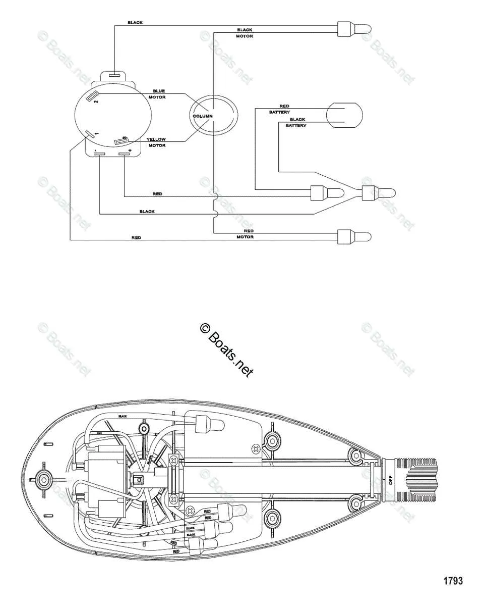
Start by ensuring proper wiring connections before any troubleshooting or upgrades. Each power source and control unit needs to be correctly mapped to its respective terminals. Carefully check the orientation and color coding of wires to avoid mismatches, as incorrect connections can cause malfunctions or even damage the system. If unsure about a specific terminal, refer to the manufacturer’s technical reference guide for clarity on pin assignments.
Pay attention to power input and output distribution. Voltage and current specifications for each part should align with the electrical demands of the engine’s components. Properly distribute the electrical load to prevent overloads that can affect performance or safety. Ensure that all circuit breakers and fuses are rated to handle peak power draws without tripping unnecessarily.
For advanced configurations, consider using a relay-based system to manage high-current demands more efficiently. This allows more precise control over electrical flow and reduces the risk of overheating. When adding extra features, always confirm that the additional components do not exceed the design specifications for the system. Monitoring equipment, such as voltmeters and ammeters, can help track real-time performance to identify issues early.
Understanding the Engine Layout
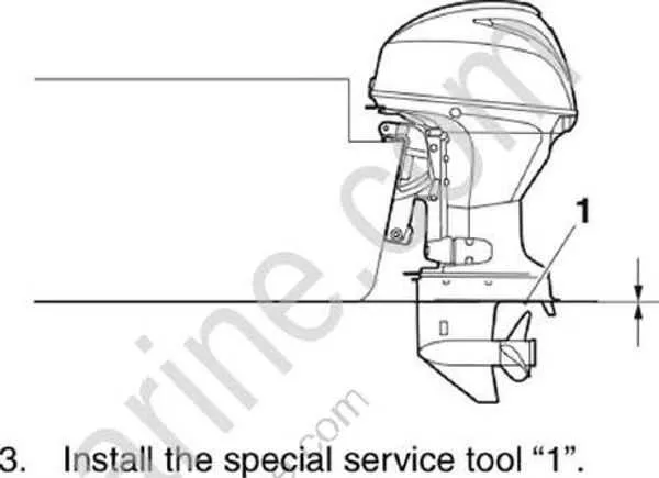
For efficient operation, ensure that the components of the propulsion system are correctly aligned. Start by confirming that the drive shaft connects seamlessly with the propeller unit. The power unit must be securely fastened to the transom, ensuring a stable connection. Proper cable routing is essential for both throttle and gear shift controls, which should be easily accessible and responsive.
Pay attention to the cooling system; the water intake should be clear of debris to prevent overheating. Ensure that the exhaust system is free from blockages to maintain proper engine performance. The fuel lines need to be securely fastened and checked for any leaks. Additionally, inspect the electrical connections regularly, making sure that the ignition and starter circuits are operating correctly.
Monitor the hydraulic system that powers the tilt and trim mechanisms. Keep the hydraulic fluid levels at the recommended specifications and look for any signs of leakage. The battery connections should be tightly secured, and the voltage levels should be checked periodically to avoid power failures.
Finally, ensure that all fasteners and bolts are tightened according to manufacturer specifications. Regularly inspect the entire assembly for signs of wear or corrosion, especially around the propeller, shaft, and exhaust components. These preventive measures will help prolong the lifespan and reliability of the propulsion system.
Understanding Key Components of a Vessel Engine
Fuel system: Ensure the fuel lines are clean and the tank is free of debris to avoid clogs that can affect performance. Regularly check the fuel filter and replace it as recommended by the manufacturer to maintain efficient operation.
Ignition system: Inspect spark plugs for wear and ensure proper gap measurement. Replace worn-out plugs to ensure a smooth start and optimal combustion. A well-maintained ignition system prevents misfires and enhances fuel efficiency.
Cooling system: The water pump circulates cooling fluid through the engine to prevent overheating. Check for leaks in the cooling lines and replace the impeller as needed to maintain proper engine temperature, especially when operating at higher speeds.
Exhaust system: Monitor the exhaust for signs of corrosion or blockages. Any obstruction can cause poor performance or damage. Ensure that exhaust manifolds and hoses are intact, and replace worn parts promptly.
Drive mechanism: Inspect the propeller for any damage, such as cracks or bent blades. A damaged propeller can affect speed and fuel economy. Additionally, regularly check the gearbox fluid level and replace it if necessary to ensure smooth operation.
Electrical components: Keep the battery charged and clean. Regularly test the alternator to ensure it is functioning properly, as a failing alternator can lead to a loss of power for essential systems.
How to Read a Boat Motor Wiring Diagram
Start by identifying the power source connections, typically marked as positive (+) and negative (-). This will ensure proper electrical flow to the system. Next, locate the ground connections; these are crucial for preventing electrical malfunctions.
Pay attention to the color coding of wires. Standard practices often use specific colors for certain functions: red for positive, black for negative, blue for signals, and yellow for lighting circuits. Make sure to match wire colors with the corresponding labels.
Trace each wire path from component to component, noting any connections to switches, relays, or fuses. Understanding the continuity of the circuit is vital for troubleshooting any issues or making modifications.
Check for any numbers or symbols next to the wires. These often represent resistance values or amperage ratings and can indicate the type of load each circuit can support. Don’t ignore these details as they can prevent damage from overloading.
Cross-reference the labels with the key or legend provided in the diagram for a more thorough understanding. Each symbol typically has a specific meaning, such as a dashed line for ground or a solid line for power, which can help in recognizing the layout of the electrical components.
Finally, confirm all connections are correctly placed, especially with regards to the ignition, fuel pump, and battery. A misconnection here can result in a malfunction or system failure. Double-checking these will save you time and potential troubleshooting down the road.
Troubleshooting Electrical Issues in Marine Engines

If your vessel’s engine is failing to start or operates erratically, begin by checking the battery voltage. A low charge is a frequent culprit and can be resolved by recharging or replacing the battery. Ensure the connections are clean and tight.
- Battery Connections: Inspect for corrosion or loose terminals. Clean the terminals using a wire brush and ensure proper torque on the connections.
- Fuse Inspection: Check all fuses for any visible damage. Replace any blown fuses, making sure to match the correct amperage rating.
Next, examine the wiring for signs of wear or shorts. Damaged cables can cause erratic behavior and even prevent starting. Ensure that no cables are frayed, kinked, or in contact with sharp edges.
- Wiring Check: Inspect all visible wires for damage. Pay close attention to areas near the engine where heat or movement could cause wear.
- Ground Connections: Verify that all ground connections are secure. A poor ground can lead to intermittent or non-functional operation.
If the issue persists, the ignition switch or relay might be faulty. Perform a continuity test with a multimeter to ensure proper functionality of the ignition components.
- Disconnect the power and remove the ignition switch.
- Use a multimeter to test the switch for continuity when in the “start” position.
- If there’s no continuity, the ignition switch should be replaced.
Finally, check the alternator for correct operation. A malfunctioning alternator may prevent the battery from charging, leading to repeated power loss. If the voltage output is lower than specified, replacement or repair is required.