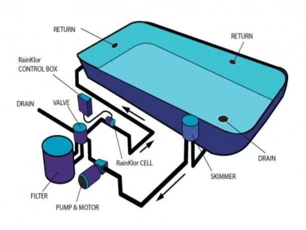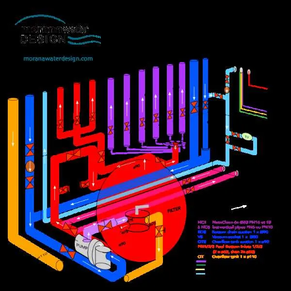
Set the flow rate at 3,500 L/h (≈925 gph) to ensure continuous turnover every 6 hours in a 21 m³ basin. Position the intake strainer 5 cm below the waterline and connect it via 50 mm PVC piping. This arrangement maintains optimal suction while reducing debris buildup.
Install a multi-stage purification cartridge with a nominal rating of 60 microns and a maximum pressure tolerance of 2 bar. Place the cartridge chamber after the pump housing to protect the motor from strain; monitor pressure via a 0–4 bar gauge and backwash when readings exceed 1.5 bar.
Use a 0.75 kW centrifugal pump capable of generating 1.8 bar at 3,500 L/h. Mount the motor on a vibration-damping base and include a 1.5 m³ expansion vessel downstream to stabilize pressure surges. Incorporate a 2-way diverter valve for winter bypass to prevent freezing damage.
Schedule maintenance every 30 days: replace the cartridge element, inspect O‑rings for wear, and lubricate the pump seal with silicone grease. Record inlet and outlet pressures at each service–target a differential of 0.3–0.5 bar for efficient operation. These precise measures guarantee clear, safe water turnover without downtime.
Water Circulation and Cleansing Blueprint

Install a centrifugal pump with at least 0.75 HP to achieve a 50 GPM turnover for a 10,000‑gallon basin.
- Intake strainer: position 3–5 ft from the basin edge, using 20‑mesh stainless‑steel screen.
- Control valves: employ 1½″ PVC ball valves rated for ≥150 PSI to fine‑tune flow.
- Purification cartridge: choose diatomaceous‑earth units with ≥60 sq ft of media surface.
- Return outlets: angle nozzles at ~30° to ensure even water agitation.
- Prime pump: fill housing until clear discharge appears, then secure lid tightly.
- Adjust valves: open slowly to maintain 45–60 PSI on the gauge without exceeding 65 PSI.
- Conduct backwash: reverse flow when pressure drops by 10–15 PSI, run until return line clears.
- Dose sanitizer: inject 0.5 ppm chlorine immediately after cleansing cycle for ongoing clarity.
How to Interpret a Pool Filter System Diagram for Installation Purposes
Start by identifying the main components: skimmer, pump, strainer basket, multiport valve, and return lines. Trace the flow beginning from the water intake point, usually marked near the skimmer inlet, progressing through the suction line toward the pump intake.
Ensure the pump connects directly to the suction side with no sharp bends that could impede flow. Verify that the directional arrows on the valve match the intended path; incorrect alignment may reverse circulation or cause pressure buildup.
Locate the pressure gauge and air relief–typically installed post-media chamber–and confirm their positions correspond to real-world mounting points. Pay attention to bypass loops and check valve symbols; these control flow rate and prevent backwash contamination during maintenance.
Cross-reference pipe diameter notations with manufacturer specs. A mismatch here leads to inefficiencies or cavitation. If a heater is included, confirm its position is downstream of the cleaning media, never before.
Ensure electrical components like timers or control boxes are shown after the pump but before any optional sanitation devices, such as UV or chlorination units. Misplacing these leads to system imbalance or safety hazards.
Key Components Identified in Pool Filter System Schematics
Start by verifying the presence of a multiport valve–this control hub directs water through various treatment stages like backwash, rinse, or circulation. Always ensure it is labeled with clear position indicators for correct operation.
Next, locate the pressure gauge; this tool monitors internal force levels and helps determine when maintenance is required. A reading above 10 psi from the baseline typically signals clogging or reduced flow efficiency.
Check for a strainer basket near the intake; it captures large debris before water enters the main cleaning unit. Ensure it has a transparent lid for easy inspection and is accessible for frequent emptying.
Identify the return line branching from the output side–it must include a check valve to prevent reverse flow, especially in elevated plumbing arrangements. If missing, install one to protect circulation integrity.
Inspect the flow meter, usually found downstream of the cleaning chamber. This component measures gallons per minute and assists in adjusting pump speed for optimal turnover rates–ideally one full cycle every 6–8 hours.
Confirm the presence of a backwash outlet pipe; it must direct waste safely away from the tank and conform to local discharge regulations. Use labeled connectors to avoid cross-contamination with clean water lines.
Troubleshooting Water Clarity Issues Using a Schematic of the Purification Apparatus
Monitor the pressure gauge: readings climbing above 28 psi–when your baseline is 12–15 psi–indicate a clogged cartridge requiring immediate backwash or replacement. Backwashing at 30 psi for 3 minutes typically restores flow rates to the standard 40–60 gallons per minute.
Inspect the debris trap: remove the lid, clear out leaves and hair every 7 days or after heavy use. A half‑inch of buildup inside the basket can reduce circulation by up to 25 %. Lubricate the O‑ring monthly with silicone grease to maintain an airtight seal.
Verify valve orientation: ensure the multiport lever points exactly to “Rinse” for 15 seconds after backwash, then switch to “Filter” position. Misalignment by even 10° can divert up to 15 % of discharge flow back into the basin, compromising water clarity.