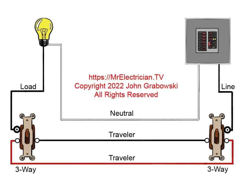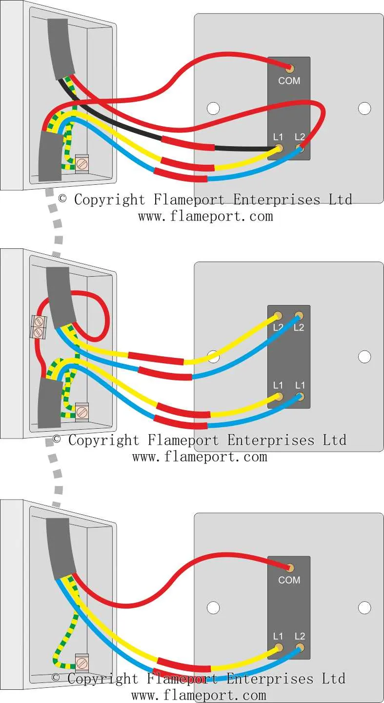
To achieve the desired setup for controlling a light from two different locations, begin by identifying the common terminal on your control devices. This terminal will serve as the central point for the electrical circuit. From here, you’ll need to connect the live wire from the power source to the common terminal, ensuring a secure and correct connection to avoid any potential safety issues.
The second terminal should be connected to the traveler wire. This will allow the device to communicate with the other unit, enabling control from an alternative position. Use the appropriate gauge of wire to handle the current load safely. For enhanced safety, ensure that the wires are properly insulated and that connections are tightly secured with wire nuts or other reliable connectors.
At the remote point, install a matching device that can interact with the first unit via the traveler wire. This will allow you to toggle the current flow, turning the light on or off from either location. Make sure that both units are correctly oriented in relation to the incoming and outgoing power paths to avoid wiring errors.
Important tip: Double-check that the circuit is de-energized before working on the setup to prevent any risk of electrical shock. Also, use a voltage tester to ensure there is no current flowing through the wires while working on the installation.
Once the setup is complete, test both units to confirm that the light can be controlled as intended from both locations. A successful installation requires attention to detail, particularly in ensuring proper connections and safety measures are followed throughout the process.
How to Connect a Dual Control Electrical Circuit

To establish a dual-control system for lighting, start by identifying the two control units. These must be connected in a series, allowing for independent control of the same light from different points. One of the terminals on the first device will be linked to the power source, while the second device will need a common terminal connected to the light fixture.
The traveler wires must be connected between both control units, ensuring the signal is routed correctly through the circuit. Make sure that the wire from the power supply enters the common terminal of the first device. From here, the signal should move through the traveler wires, reaching the second control unit.
At the second device, connect the traveler wires to the terminals, with the common terminal linked to the light fixture. This ensures that the circuit is completed and the light can be controlled from either point in the circuit.
Ensure all connections are properly secured, and test the system for functionality by switching each control unit to test the flow of electricity. If the light operates as expected from both locations, the setup is complete and safe for use.
Understanding the Wiring Connections for a Three-Way Switch
To ensure proper functionality, connect the traveler terminals between the two control devices. The common terminal on each should be linked to the appropriate conductor leading to the light fixture or power source. The ground connections must be established to provide safety from electrical faults.
Important: One device must have the power supply coming in through its common terminal, while the other should have the fixture connected to its common terminal. This configuration allows the current to be directed between the two devices, enabling control over the fixture from different locations.
Make sure to test the setup after installation to verify that switching between the two locations correctly toggles the light. Properly secure all connections to avoid loose contacts that could cause malfunction or potential hazards.
Additionally, if dealing with more complex configurations, always double-check the wiring against the device’s manufacturer specifications to prevent errors.
Step-by-Step Guide to Setting Up the Controls
To begin, ensure you have the right tools: a screwdriver, electrical tape, wire strippers, and a voltage tester. This guide will help you properly install the control mechanism with minimal effort.
- Turn off the power: Disconnect the power at the breaker to avoid electrical shock.
- Identify the terminals: Locate the terminals for the incoming line, the common terminal, and the traveler connections on the device. Typically, the common terminal is marked differently.
- Connect the incoming line: Attach the live (hot) wire to the common terminal on the first control unit.
- Prepare the traveler wires: Strip the ends of two wires that will run between the control units. Connect one wire to each of the traveler terminals on the first device.
- Set up the second control: At the second device, connect the traveler wires to the traveler terminals. The common terminal on the second unit should be connected to the load wire going to the light fixture.
- Check the ground wire: Ensure the ground wire from both units is properly connected to the grounding screw or wire.
- Test your work: Before securing everything in place, test the system by turning the power back on and checking the operation of the device. The light should turn on and off from either unit.
After confirming functionality, secure the controls in their boxes and cover with faceplates. Double-check that everything is tightly connected and that no wires are exposed.
Common Installation Mistakes to Avoid in Multi-Switch Configurations
Incorrect connection of traveler wires is one of the most frequent errors. Ensure that both traveler terminals are properly connected to the respective terminals on each device, as misplacement can prevent proper operation or lead to a malfunctioning circuit.
Overlooking ground connections is another critical mistake. Every device must have a proper ground connection. Failing to connect the ground wire to the box or switch terminal can cause electrical hazards.
Using incorrect gauge wire can result in overheating or even electrical fires. Always use wire gauges that meet the manufacturer’s specifications for the circuit. Most setups require 14 or 12 gauge wire, depending on the load.
Misunderstanding the common terminal can lead to functionality issues. The common terminal should always be connected to the power source or load, not to a traveler wire. Check the terminal label and double-check before making the final connections.
Inadequate box space is a problem often overlooked. Ensure the junction box has enough space to accommodate all wires and devices. Overcrowding the box can lead to short circuits or wire insulation damage, increasing the risk of electrical failure.
Neglecting to turn off power is an easily avoidable mistake. Always verify the power is off before working with any electrical components. Even experienced electricians can make this mistake, risking shock or injury.
Improper use of backstabbing should be avoided. While convenient, backstabbing terminals can be unreliable over time. Instead, use screw terminals to secure wires, ensuring a more stable and lasting connection.