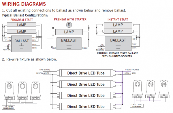
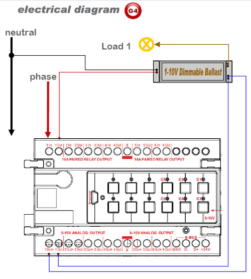
For use with dimmable electronic ballasts that use a 0>10VDC dimming signal, . Connect lead wires per WIRING DIAGRAM as follows: Twist strands of each. dimming ballasts and controls lets you accomplish these goals with a variety of products ..
See page for Dimensions and Wiring Diagrams. All models are . Lutron offers several different ways to install and control our dimming ballasts.
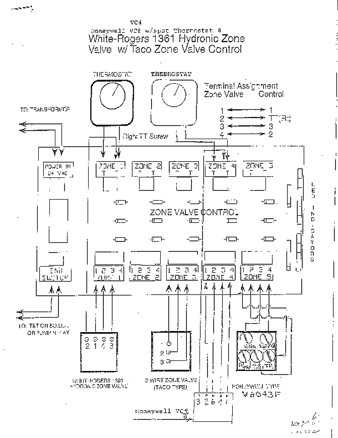
See the wiring diagrams in the. Appendix for more information. • 3-wire control. For use with dimmable electronic ballasts that use a 0>10VDC dimming signal, .
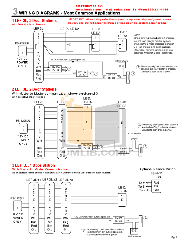
Connect lead wires per WIRING DIAGRAM as follows: Twist strands of each. When retrofitting dimming ballasts into fixtures that originally had Instant Start ballasts, the sockets MUST be Connect wires per WIRING DIAGRAM as follows .Whether you are looking to reduce energy costs, increase comfort, or manage light control solutions, Lutron products offer the flexibility you need with the energy savings you want.
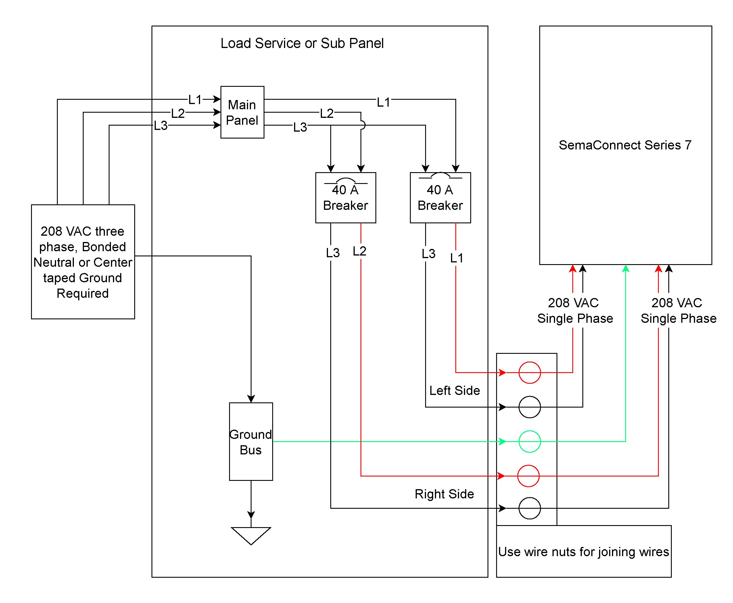
Dimming ballasts are available for fluorescent tubes and CFLs that use an external ballast. These ballasts are usually rapid start or programmed start, and have a good dimming range. 2 Lamp Dimming Ballast Wiring Diagram.
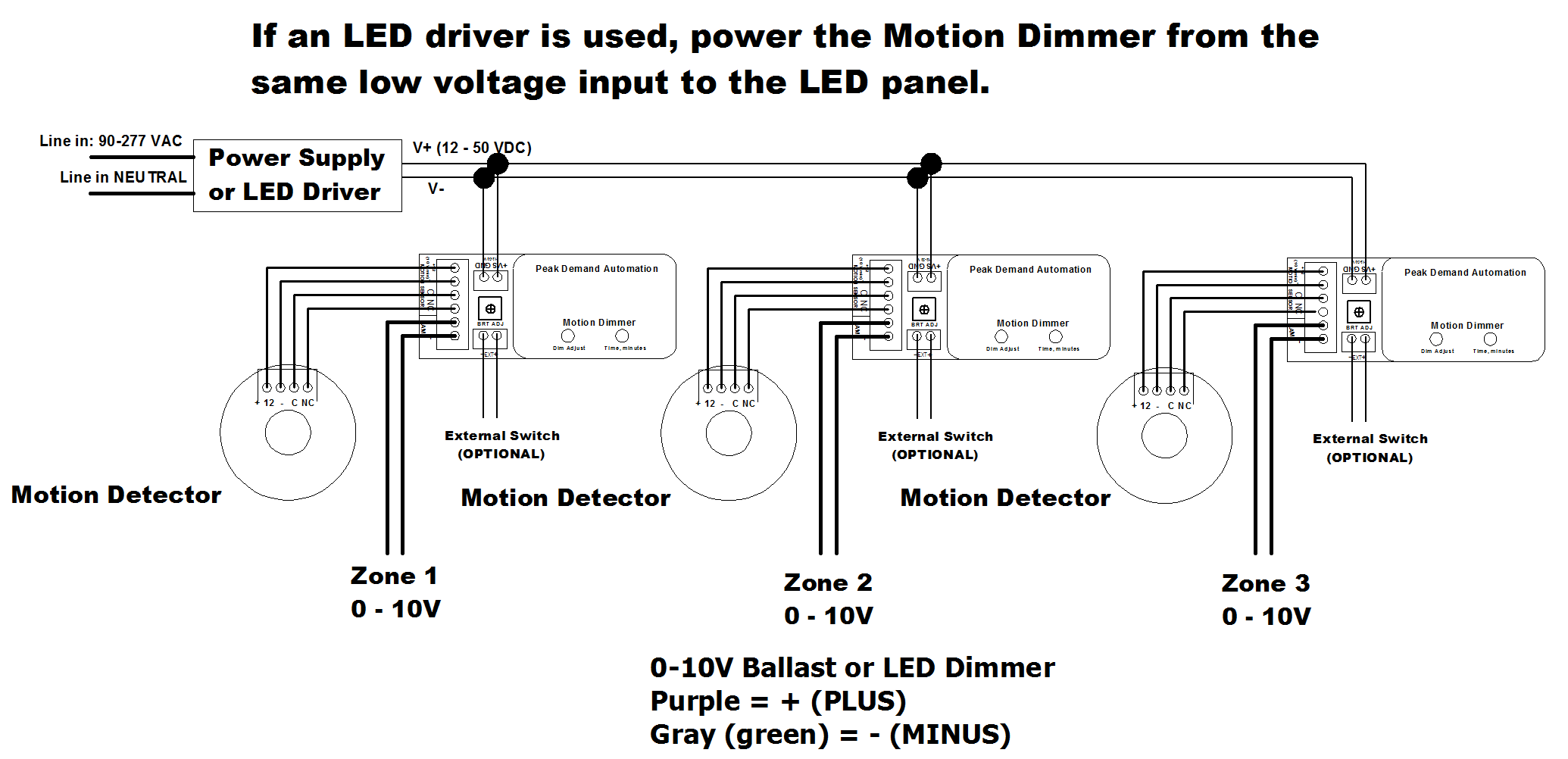
Using Advance Mark 7 or Mark 10 dimming ballast and dimmer switch. 2 lamp series ballast wiring.
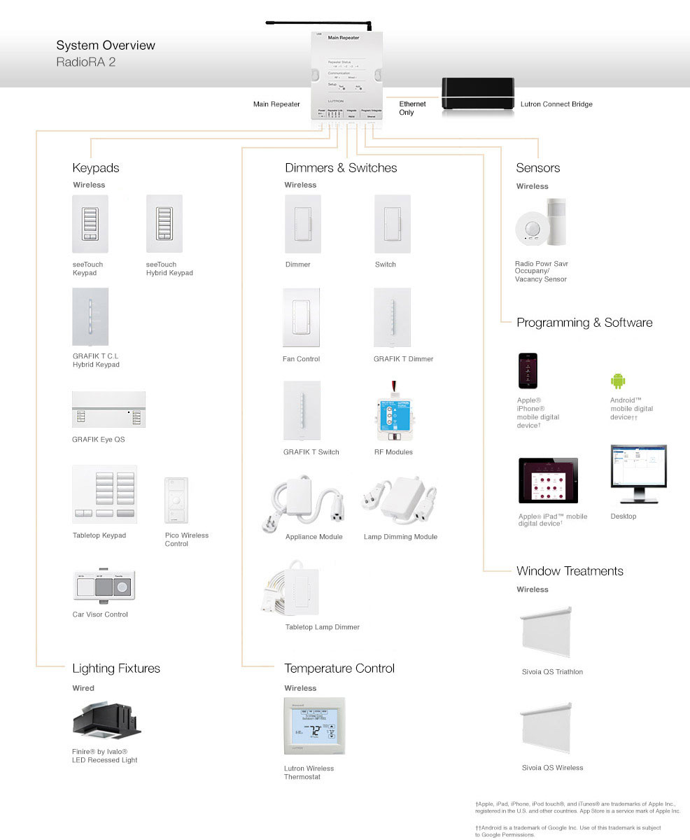
Often, dimming ballasts and dimming LED power supplies use V control signals to control dimming functions. In many cases, the dimming range of the power supply or ballast is limited. If the light output can only be dimmed from % down to 10%, there must be a switch or relay available to kill power to the system and turn the light.
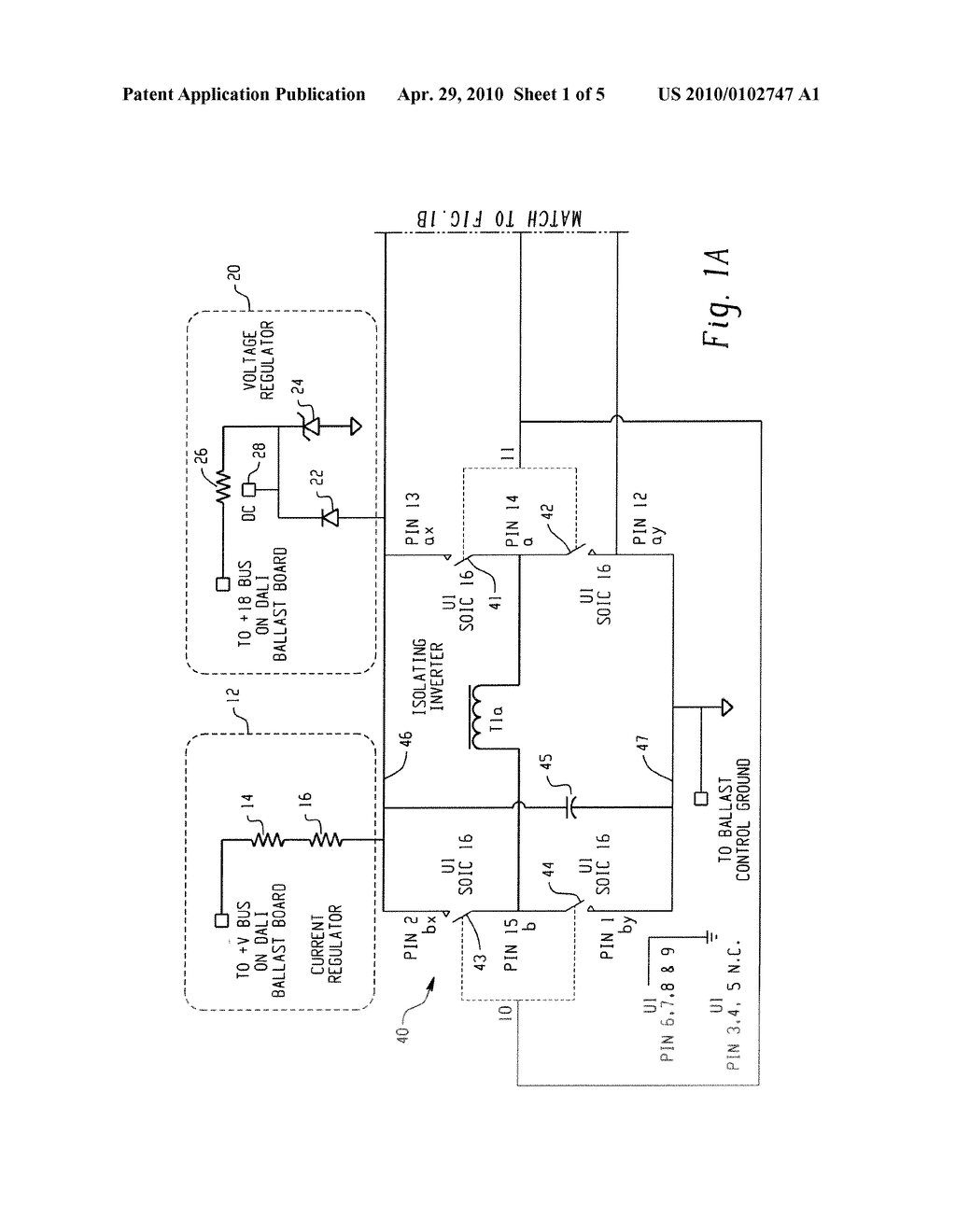
Lutron Dimming Ballast Wiring Diagram With Dimmer Switch In Diva, size: x px, source: schematron.org Below are some of the leading drawings we obtain from numerous sources, we wish these images will be useful to you, and with any luck really relevant to just what you desire concerning the Lutron Dimming Ballast Wiring Diagram is. 6 Philips Advance Ballast Quick Guide T5 and T5/HO Centium Programmed Start Fluorescent Ballasts Offered in a broad range of fixed light output and dimmable versions, these energy-efficient ballasts are ideal for applications such as hotels, offices, schools, restaurants, and specialty and.Mark 7 V Fluorescent Dimming gear – Philips LightingInspirational Lutron 3 Way Switch Wiring Diagram – Diagram | Diagram
