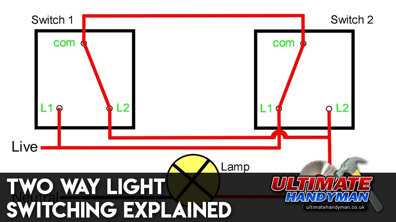
The L1 and Coms just need to have the same wiring on the new dimmer switch.
I’ ve not done it yet but got my answer from another forum. The L1 and Coms just need to have the same wiring on the new dimmer switch.
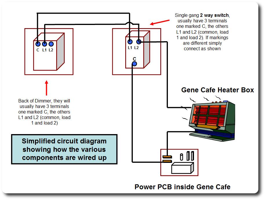
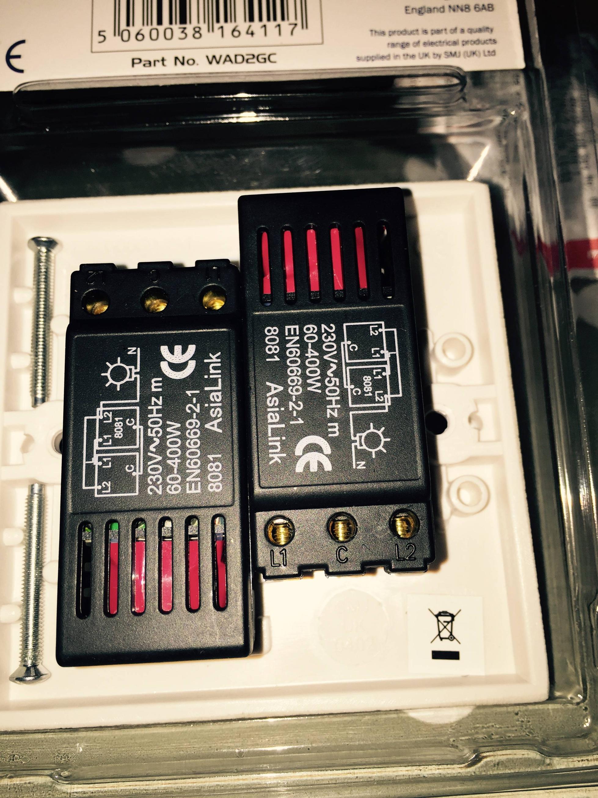
I’ ve not done it yet but got my answer from another forum. Dimmers look slightly different to standard switches being much more chunky. They usually come supplied with a common(C), Line out(L1) and Line out(L2).
Two way switches have a COM terminal as well as L1 and L2 terminals. Check out the diagram below that shows how to way a three way switch: When wiring a Lightwave RF master dimmer to a slave, the voltage isn’t mains voltage it’s. Two way switches have a COM terminal as well as L1 and L2 terminals.
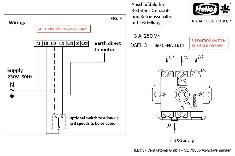
Check out the diagram below that shows how to way a three way switch: When wiring a Lightwave RF master dimmer to a slave, the voltage isn’t mains voltage it’s.There are no markings on the back of the dimmer switch, and on the back of the new switch I’ve got 3 points -COM, L1 and L2. Logic would say that the 2 wires should go in COM and L1 or L2, but the problem is both wires are the same colour, and there aren’t any .
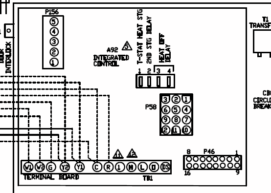
I have tried wiring in the two commons then wiring switch one L1 connection and switch 2s L2 connection then bridging the L2 on switch one and L1 on switch two, I can get the two switches to work this way but only if the partner switch to the 2 way light is left on. Figures 3 and 4 which show typical 2-way circuits. Remove your old switch and copy the wiring configuration for the dimmer.
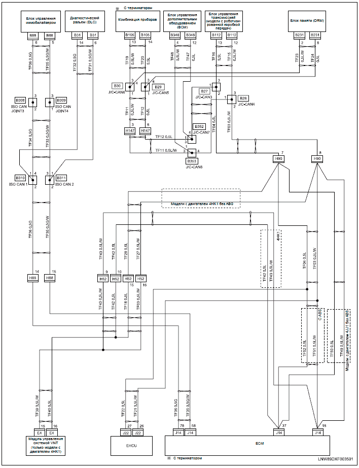
Remove your old switch and copy the wiring configuration for your dimmerswitch. The wire(s) fitted in the “common” terminal of the old switch should be fitted into the “C” terminal of the dimmerswitch.
L1 and L2 Motor Wiring The L symbol designation refers to the Line, or the incoming circuit wires that provide the power for the motor. For example: L1 and L2 indicate that the motor voltage may be .

May 06, · not being funny, but it’s got the fraking wiring diagram on the back of the dimmer L1 to L1 C to C L2 to L if you want more specific answers then we will need photo’s of the wiring to the switches already installed.Wiring A Double dimmer switch | DIYnot ForumsWiring a dimmer switch | AVForums