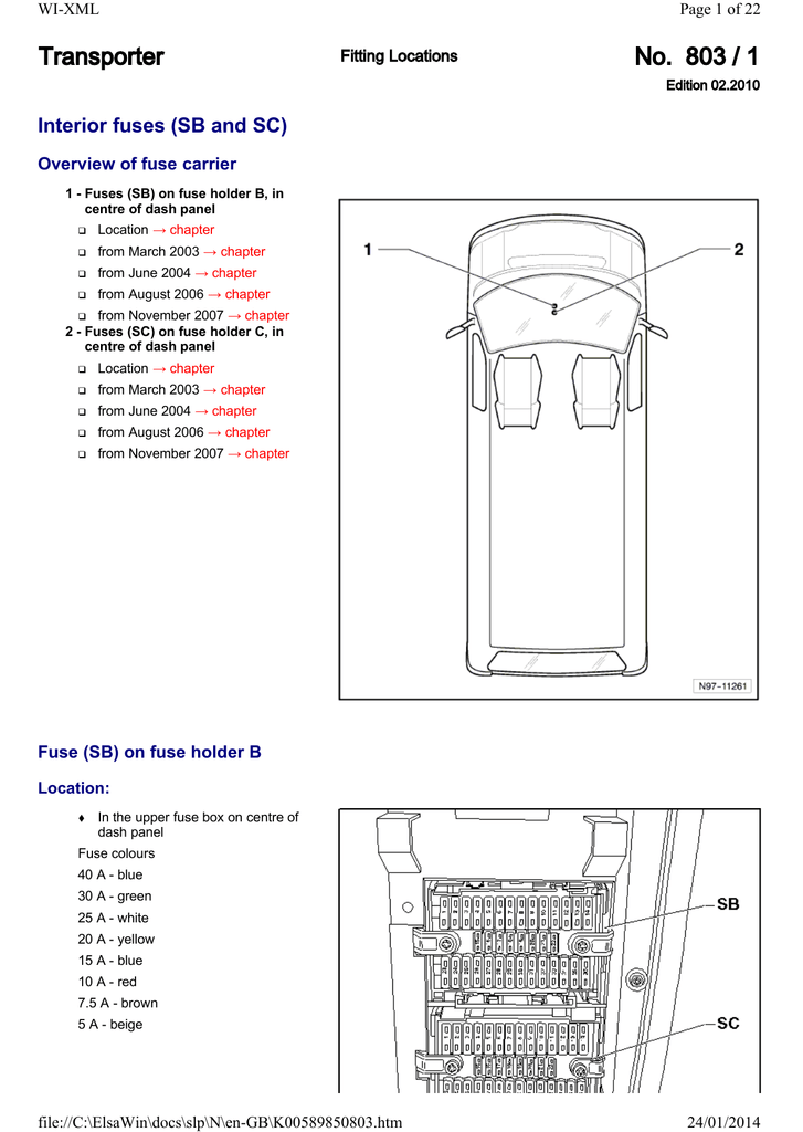

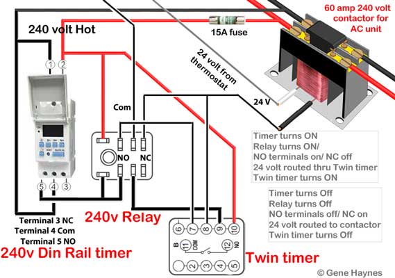
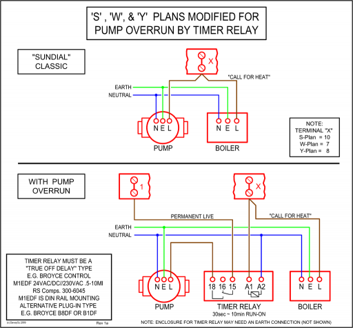
This diagram solves problem without compromising integrity of AC motor or Any programmable timer will do the job but din rail timers are available in 24 volt, and wires from thermostat is connected to the com terminal on the din rail timer. DRTS is a programmable digital timer switch with relay output.
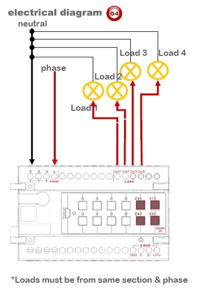
It can be The DIN rail mount of this timer switch makes it suitable for power Wiring Diagrams. Please read all installation instructions before using your SeriesOne DR Timer.
Install the relay on the DIN rail (as shown in fig.1). Wire the relay to the input side.
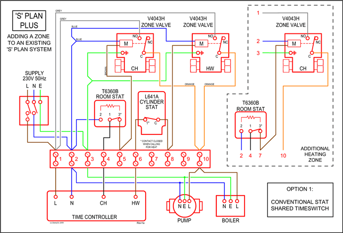
install 2 cable go directly to the pump the third is connected in both sides of the switch Now, I bought a din rail timer to automatically control the pump. This timer has 2 can you please confirm your diagram with this info?.
install 2 cable go directly to the pump the third is connected in both sides of the switch Now, I bought a din rail timer to automatically control the pump. This timer has 2 can you please confirm your diagram with this info?.Jan 15, · This is a cheap general purpose DIN rail mounting time switch I bought from eBay, purely to take a look inside to assess the quality of construction.
Universal TR Series staggered terminal locations allow access to lower-level terminals after wiring. Universal TR Series compact, DIN rail mountable case reduces panel size.
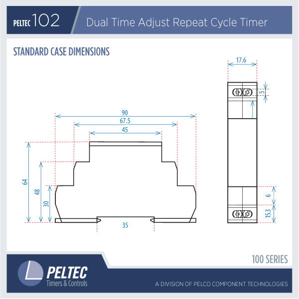
TMRP Series thumb-wheel setting design allows for quick selection and review of multiple timing functions and timing ranges. DIN rail time switches control the on and off mechanisms of equipment, lighting components and heating or cooling applications. A DIN rail is a universal mount used as a modular platform to add components like circuit breakers and time switches.
Products declared as Obsolete are no longer available for purchase from Crouzet Control. Obsolete products may not be in printed catalogs, but you may look for product specifications at the Crouzet Control on-line catalog.
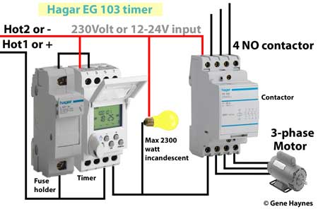
To install on DIN rail To remove from DIN rail xxx06x WIRING DIAGRAM Wire Size Maximum wire strip length in ( mm), maximum in ( mm). (B) Terminals 5 Terminal screws Pozidriv #1, 3/16 in ( mm). Important Considerations Be sure to use input and output voltages within operating ranges.
LED indicates only input status. It does.How to wire timersPanel Mount/DIN Rail Timers
