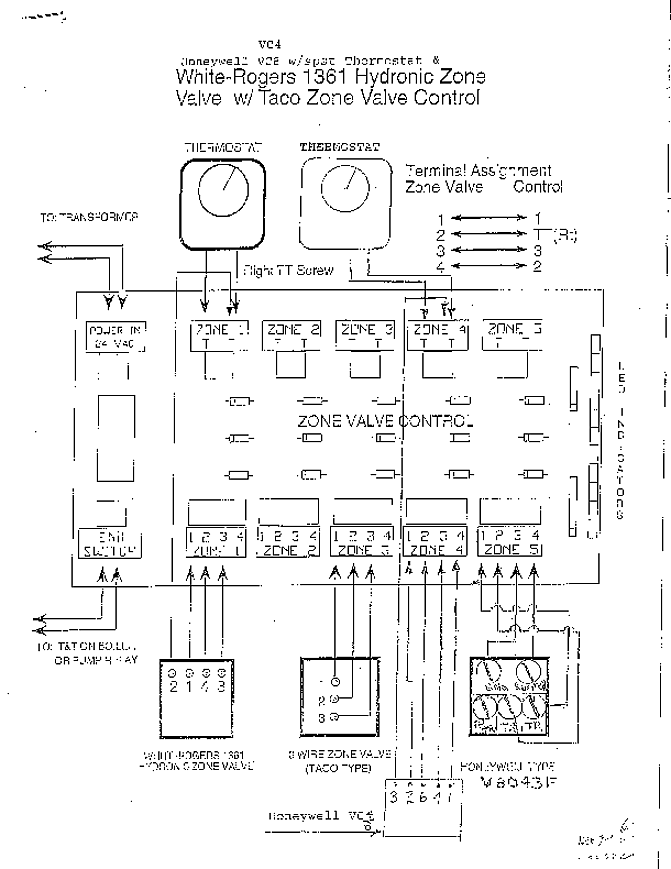

Your D’MAND Kontrols® System “PF” installation kit includes: o Adapter with IFC valve one (1) (C models only, Pre-installed on units Present). Vitotronic , GC1B Installation and Service the instructions listed below and details printed in this manual can cause ..

External demand burner stage 2. rU C3.
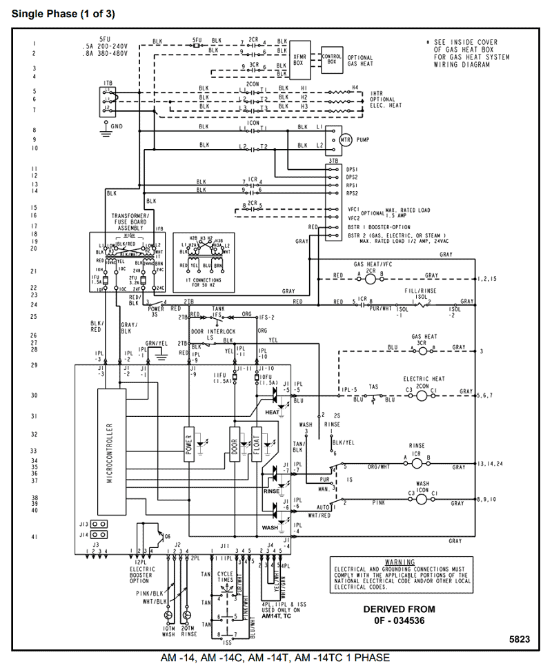
Control mode. Communication error, extension AM1.
Check connections. C This D’MAND KONTROLS® System includes an electronic circuit board, thermosensor mounted in composite volute, 3/4″ CPVC threaded connections.
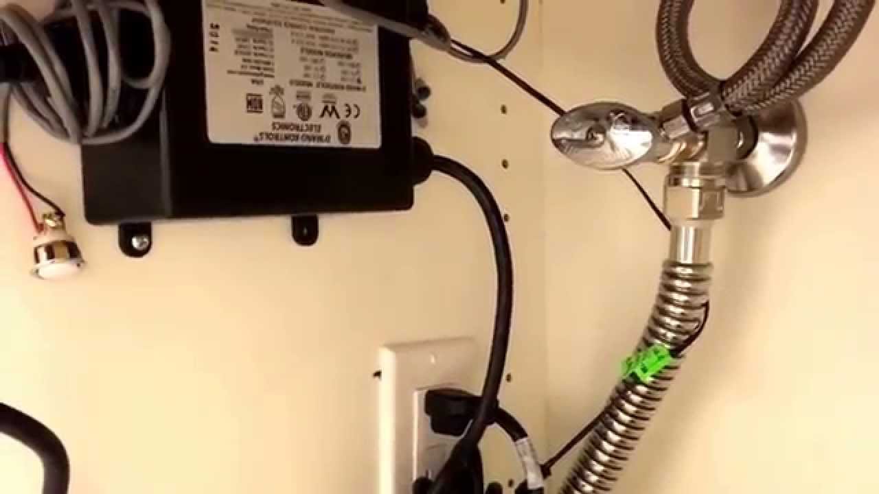
C This D’MAND KONTROLS® System includes an electronic circuit board, thermosensor mounted in composite volute, 3/4″ CPVC threaded connections. and More!. Act D’MAND Kontrols System 3-Speed Pump Model C Additional Chrome Hard Wired Activation Button: .
Installation Manual.Browse by All Products Use this list to browse all the products available, use the Category Box to the upper left to find by category type, or the the Quick Search Box to search by keywords. C This D’MAND KONTROLS ® System includes an electronic circuit board, thermosensor mounted in composite volute, 3/4″ CPVC threaded connections, and internal check valve.
Recommended for use with dedicated return lines in buildings up to 4, sq. ft.
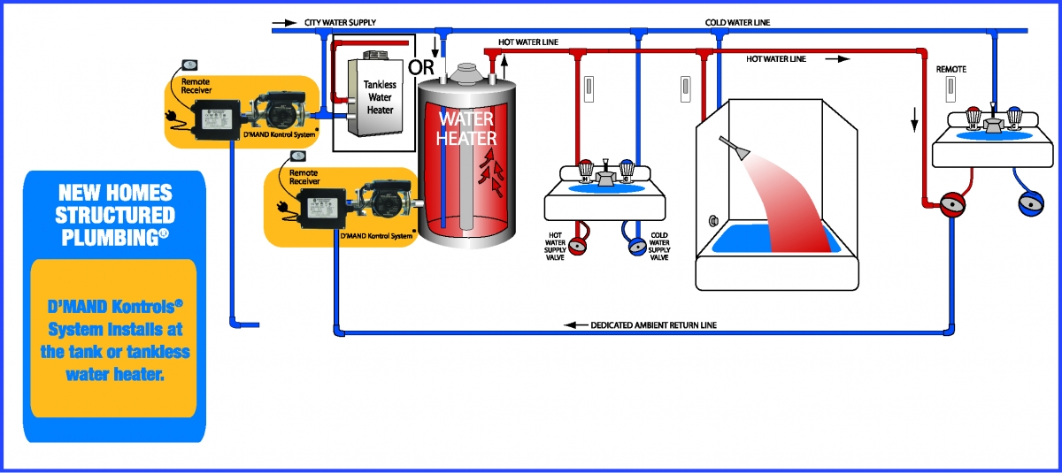
with tank water heaters. Or pipe runs up to lineal ft. with tankless water heaters.Act D’MAND Kontrols System 3-Speed Pump Model CControlled Hot Water Recirculation System – Demand Recirc Pump – schematron.org
