can indicate problems with the installation or adjustment of the ED , ..
SOLUTION: Confirm that the electric strike is wired according to the diagrams shown. DORMA ED Swing Door Operator control system, the ED is DORMA’s most advanced low-energy swing door power operator.
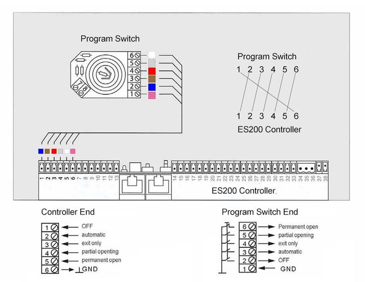
Parts and diagrams MAGNETIC LOCK INSTALLATION INSTRUCTIONS PLEASE READ BEFORE INSTALLATION ALARM REVIEW THE WIRING DIAGRAM ON PAGE 4 2. DORMA ED SERIES Service Manual ED J ED T software level M .

View and Download Dorma ED J installation instructions manual online. GROUND Typical wiring diagram for the ED with ES +12VDC OPEN. DORMA ED Series low energy operators with selectable low energy or power assist.
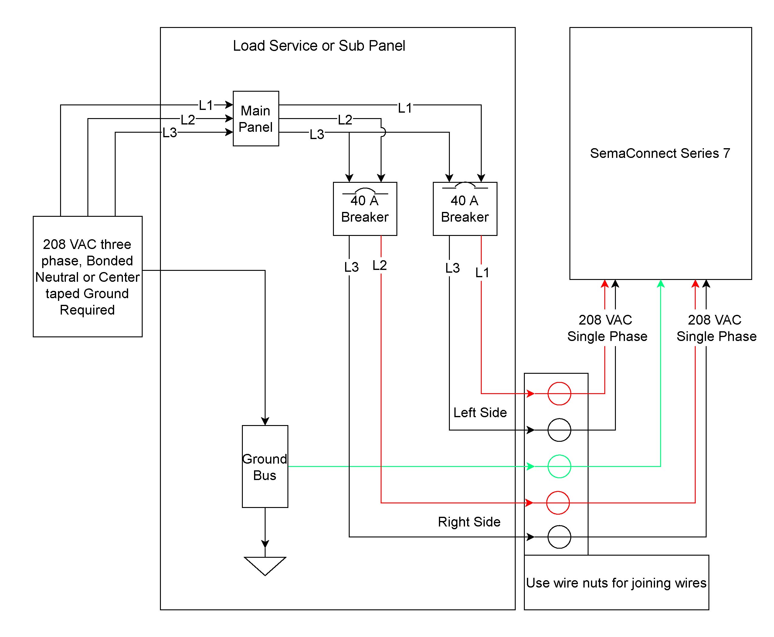
offers assistance with point to point wiring diagrams. Please.When incorporating the ED into a system with other electri – cal components, DORMA’s Technical Services Department offers assistance with point to point wiring diagrams. ED T; Dorma ED T Manuals Manuals and User Guides for Dorma ED T.
We have 1 Dorma ED T manual available for free PDF download: Installation Instructions Manual. Dorma ED T Installation Instructions Manual (28 pages) Ed Controller Module Diagram DORMA ED Low Energy Operators 3 The ANSI A DORMA ED is a surface closer based low energy power operator that precisely senses the door environment and responds appropriately.
The ED is designed for manual openings that occasionally require automatic opening. The Americans with Disabilities Act (ADA) heightened awareness.
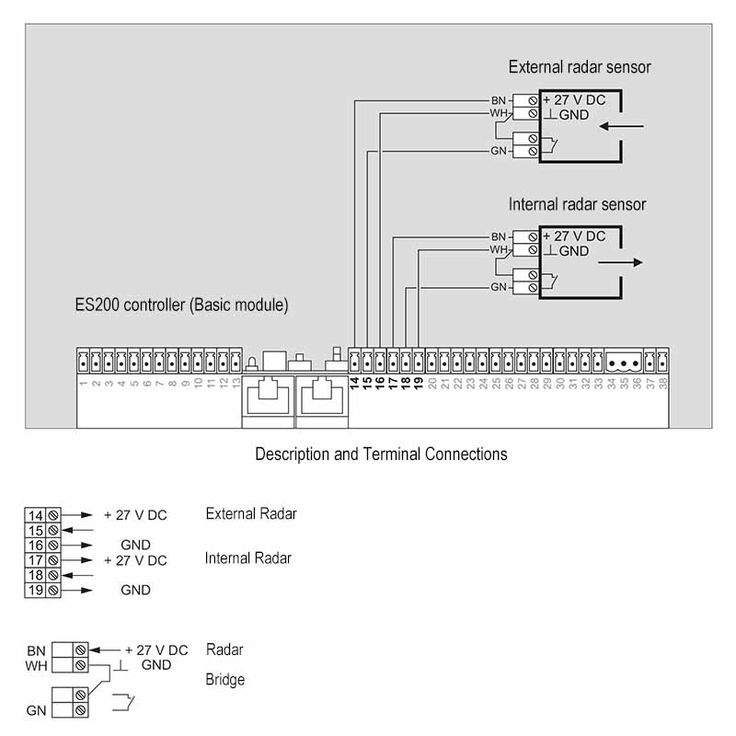
The DORMA ED low energy power operator was designed to make doors accessible, while still providing the good operating characteristics of a manual door closer. GROUND Typical wiring diagram for the ED with ES +12VDC OPEN TRIGGER Power Supply and ES exit device.
BUSY SWING (SAFETY) VESTIBULE ED ES POWER TRANSFER ES EXIT DEVICE ES POWER SUPPLY TURN OFF VAC POWER BEFORE (IN) (IN) MAKING ANY CONNECTIONS OR SERVICE.DORMA ED SERIES Service ManualDORMA ED J INSTALLATION INSTRUCTIONS MANUAL Pdf Download.