Integrate this Power Supervision Relay into your home security systems for reliable safety DSC RM-1 Power Supervision Relay For Smoke And Co Sensors.
RM-1,DSC 12V Relay Module – Buy online at Aartech Canada. RM-1,DSC 12V Relay Module – Buy online at Aartech Canada.
Recent DSC RM1 – 12VDC End of Line Relay questions, problems & answers. Free expert DIY tips, Relay dsc diagram contact need · DSC RM1 – 12VDC.
DSC RM-1 Power Supervision Relay for 4-wire Smokes. This is a four-wire power supervision relay from DSC for four-wire smoke detectors.
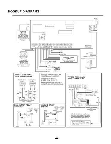
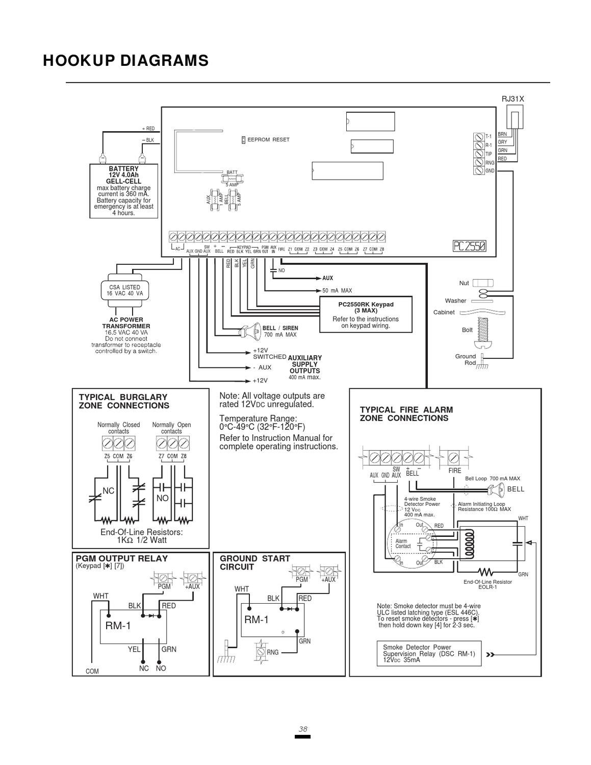
You will install this.A DSC RM-1 Relay should be used to connect power to the smoke detectors; refer to the hook-up diagram below. Power wiring from the AUX+ / PGM terminals should be supervised using a DSC RM-1 Relay connected after the last smoke detector. The RM-1 normally-open contacts (closed with power applied) should be wired in series with.
A DSC RM-1 Relay should be used to connect power to the smoke detectors; refer to the hook-up diagram below. Power wiring from the AUX+ / PGM terminals should be supervised using a DSC RM-1 Relay connected after the last smoke detector.
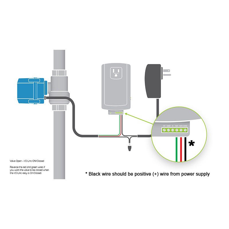
The following diagram below shows its pin assignments. Legend: DInL – digital input low, channeln DInH – digital input high, channel n GND -ground NC n – normal close pin of relay n NO n – normal open pin of relay n COM n – common pin of relay n.
Nov 13, · I purchased a DSC panel and I have four four wire smokes. Do I need to purchase a separate RM-1 relay or is it included in the panel.
18 yrs ago I installed a Napco Magnum panel, and I am not an electrician. The supervision relay is installed at the end of the detector power circuit. A break in the detector power circuit or a loss of power de-energizes the power supervision relay, opening the contacts and causing a trouble annunciation at the fire alarm control unit.5/5(7).DSC Rm-1 Supervisory relay12VDC End of Line Relay
