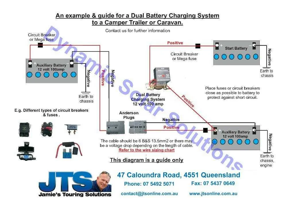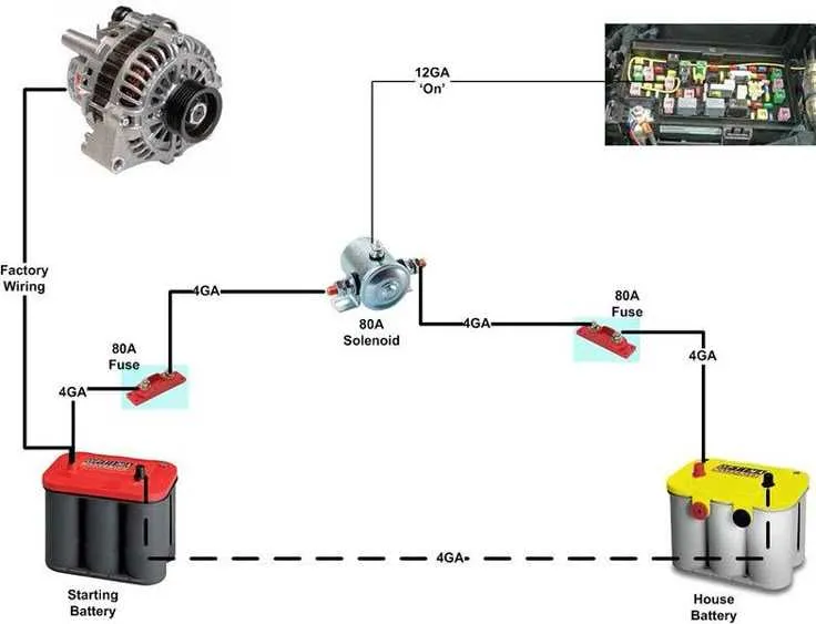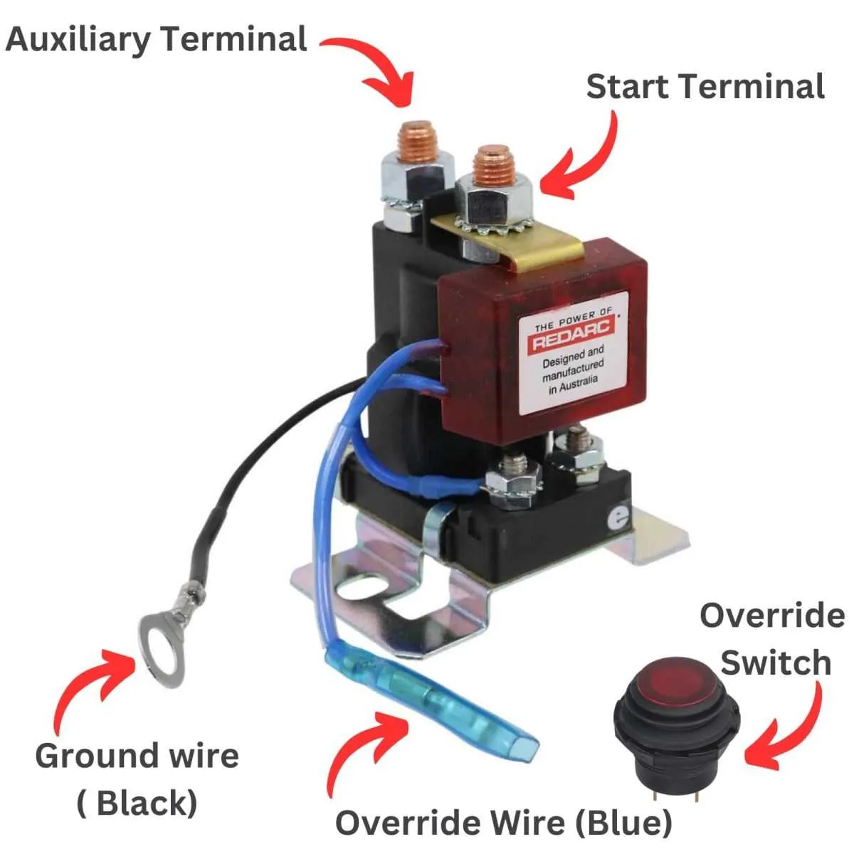
Always isolate the auxiliary unit from the main power supply using a high-quality voltage-sensitive relay. This ensures automatic disconnection when the ignition is off, preventing drain on the primary energy source. Choose a relay rated for at least 100A continuous current to handle typical loads like refrigeration or inverters.
Use thick-gauge cable (minimum 4 AWG for distances under 3 meters) between the main and secondary storage units. Secure all connections with crimped ring terminals and protect them with heat-shrink tubing to reduce resistance and prevent corrosion over time.
Install a fuse within 30 cm of each storage unit to safeguard against short circuits. A 100A fuse on both ends is standard for most 12V configurations. Place the protection devices in accessible locations to facilitate maintenance or replacement.
Ground both units independently to the chassis using clean, rust-free mounting points. Avoid relying solely on the frame as a return path to minimize voltage drop and reduce the risk of failure due to poor conductivity.
If using solar panels or DC-DC chargers, connect them directly to the secondary energy source. These devices must be compatible with smart alternators and support adjustable charging profiles for different chemistries, such as AGM or LiFePO4.
Parallel Configuration for Auxiliary Power

Connect the positive terminal of the main cell directly to the positive post of the secondary unit using a thick gauge cable (minimum 4 AWG) to ensure low resistance. Place a 100A fuse within 12 inches of each power source to prevent short circuits.
Ground each unit separately to the vehicle chassis using dedicated connections to minimize voltage drop and avoid grounding loops. Use 4 AWG or thicker wire with crimped ring terminals, bolted to clean, paint-free metal surfaces.
Install a voltage-sensitive relay (VSR) between the positive lines. Choose a model rated for 12V systems and capable of handling at least 120A continuous. This device isolates the second unit during engine-off conditions, preventing main cell depletion.
Secure all lines with loom tubing and zip ties along frame rails or existing cable paths. Avoid sharp bends and high-temperature zones. Use rubber grommets when passing through bulkheads or metal panels.
Label each connection clearly using heat-shrink markers or cable tags. Conduct voltage and continuity checks after installation. Verify that the alternator supplies charging current equally to both units when the engine is running.
How to Wire a Dual Battery System with an Isolator

Start by mounting the secondary power cell in a secure, ventilated location near the primary unit to minimize cable length. Use at least 4 AWG copper wire to handle high current flow efficiently. Connect the negative terminal of the auxiliary unit directly to the vehicle chassis or the main ground point.
Install a voltage-sensitive relay (VSR) or manual isolator between the positive posts of both units. Place a 100A to 150A fuse within 30 cm of each power source on the positive cable to protect against short circuits. Route the cable from the main unit’s positive side to the isolator’s input, and then from the isolator’s output to the auxiliary cell’s positive terminal.
If using a VSR, ensure it activates above 13.3V and disconnects below 12.8V to prevent draining the starter source. Secure all connections with crimped lugs and heat-shrink tubing. Verify continuity and voltage levels with a multimeter before starting the engine. Check that the isolator engages only after the engine begins charging.
Choosing the Right Cable Gauge for Dual Battery Connections
Use 2 AWG copper wire for setups with runs up to 10 feet carrying currents of 100–150 amps. For distances beyond 10 feet or higher current loads, opt for 1/0 AWG to minimize voltage drop and prevent overheating.
When amperage exceeds 200 amps or the cable length surpasses 20 feet, select 2/0 AWG for maximum efficiency. Always base wire size on both current demand and total cable length (positive and negative combined).
Avoid aluminum conductors due to their higher resistance. Ensure all terminals are crimped with a hydraulic tool and covered with heat shrink for corrosion protection. For circuits under 50 amps and short runs (under 5 feet), 6 AWG may suffice, but verify with a voltage drop calculator before installation.
Placement and Mounting Considerations for Second Power Source

Install the auxiliary energy storage unit as close as possible to the main power distribution panel to minimize voltage drop and cable length. Ensure the mounting location provides:
- Stable and vibration-resistant support, preferably using rubber isolators or cushioned brackets.
- Good ventilation to prevent overheating during charging and discharging cycles.
- Protection from exposure to moisture, dirt, and corrosive substances by using sealed enclosures or mounting within a protected compartment.
- Easy access for inspection, maintenance, and cable connection adjustments.
When securing the unit:
- Use stainless steel or corrosion-resistant fasteners to avoid rust formation.
- Ensure the mounting surface is flat and rigid to prevent mechanical stress on terminals and wiring.
- Maintain clearance around the power storage device for heat dissipation–at least 2–3 inches on all sides.
Cable routing should avoid sharp bends and high-temperature zones, keeping the conductors away from moving parts and fuel lines. Additionally, install a fuse or circuit breaker as close as possible to the positive terminal of the secondary energy cell to protect against short circuits.