To efficiently set up a two-unit airflow system, connect each unit in parallel to ensure synchronized operation. The power source should be connected to both devices through a central terminal, with each having an independent connection to ground. Use quality insulated cables to avoid overheating and short circuits. Ensure that the control switches are wired in such a way that each unit can be individually controlled if needed.
Ensure Proper Voltage Distribution: The voltage supply must be evenly distributed between the two devices. A dedicated relay for each unit can help balance the load. When one unit is operating under full capacity, the second one should not experience an increase in its voltage or power draw.
Phase Sequence is Key: Verify the phase sequence before connection. Misalignment can lead to malfunction or reduced efficiency of the system. Proper phase identification ensures that both devices function in harmony, reducing wear and tear over time.
For optimal performance, use connectors that support the current requirements of both systems, and avoid daisy-chaining wires, as this can cause uneven power distribution. This setup maximizes airflow efficiency and prolongs the lifespan of the units.
Connecting Two Cooling Units Together
When setting up two separate cooling units, ensure they share a unified power supply and control mechanism for synchronized operation. Here are the key steps for an effective setup:
- Use a single power source to avoid overloading circuits. A fused connection helps protect both units from electrical surges.
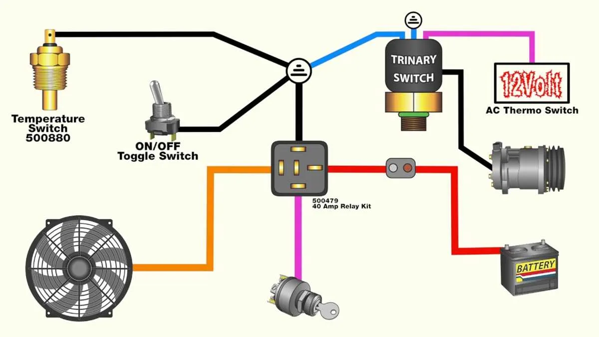
- Implement a relay for controlled activation. This allows one unit to trigger the other based on specific temperature readings or switches.
- Wire both systems in parallel, ensuring equal voltage distribution. This keeps the power flow balanced between the two units.
- For safety, integrate thermal protection devices in both circuits. Overheating can cause damage to components, so automatic shut-off mechanisms are essential.
- Utilize proper connectors and gauge wires. Use heavy-duty cables that can support the amperage needed for both units operating simultaneously.
Incorporating these tips will result in a more efficient cooling solution that operates seamlessly without overloading or overheating issues.
Understanding the Configuration for Two Cooling Units in Parallel

When connecting two cooling units in parallel, it’s crucial to ensure both are wired correctly to prevent voltage drops or overcurrent. Start by linking the positive terminals of both units to the same power source, ensuring that each unit receives equal voltage. Then, connect both negative terminals to a common ground. This configuration ensures both units operate at the same voltage, maintaining balanced performance and efficiency.
If the units have different power ratings, calculate the total current draw to avoid overloading the circuit. Consider using a fuse or circuit breaker rated for the total current to protect the setup. Proper wire gauge selection is also important to handle the combined load, ensuring safety and preventing overheating.
In addition, pay attention to the manufacturer’s specifications regarding the maximum allowable current for each unit. For larger units, it may be necessary to use thicker wires to reduce resistance. If you’re connecting the units to a controller, ensure the controller can handle the combined load and that it’s designed for parallel connections.
Step-by-Step Guide to Connecting Two Cooling Devices with One Power Supply

Start by determining the voltage rating of your cooling units. Ensure that both devices are rated for the same voltage level, typically 12V or 24V, depending on the model. Use a multimeter to check the output from the power source to confirm compatibility.
Step 1: Connect the positive terminal of the power supply to the positive terminals of both units. Use an appropriate gauge wire to handle the current draw, ensuring the wire can handle the total amperage of both devices combined.
Step 2: Now, connect the negative terminal of the power supply to the negative terminals of both devices. Again, ensure the wire is sufficiently rated for the combined current.
Step 3: Use a Y-connector or a terminal block to safely distribute the power from the single source to both units. This will prevent accidental shorts and provide a secure connection. Ensure the connector is rated for the amperage required by both devices.
Step 4: Secure all connections with electrical tape or heat shrink tubing to prevent any accidental exposure of wires. Check for any potential shorts or exposed wires that might cause issues when powered on.
Step 5: Power on the system and test both units. Use a multimeter to verify proper voltage is reaching each device. Check for any overheating or unusual noise from the devices that might indicate an issue with the power distribution.
Important Note: If one of the devices requires a different power configuration (such as a different voltage or current draw), consider using a voltage regulator or separate power source for that unit to prevent damage.
Common Troubleshooting Tips for Dual Fan Wiring Issues
Check for proper power supply connections to the cooling components. Inconsistent voltage or poor contact can lead to malfunction. Use a multimeter to verify the correct input voltage at both terminals.
Test each component individually before proceeding with complex diagnostics. Disconnect each motor and check functionality separately to rule out internal failures.
Ensure grounds are properly connected to prevent erratic behavior. A loose or inadequate ground connection can result in intermittent operation or no response at all.
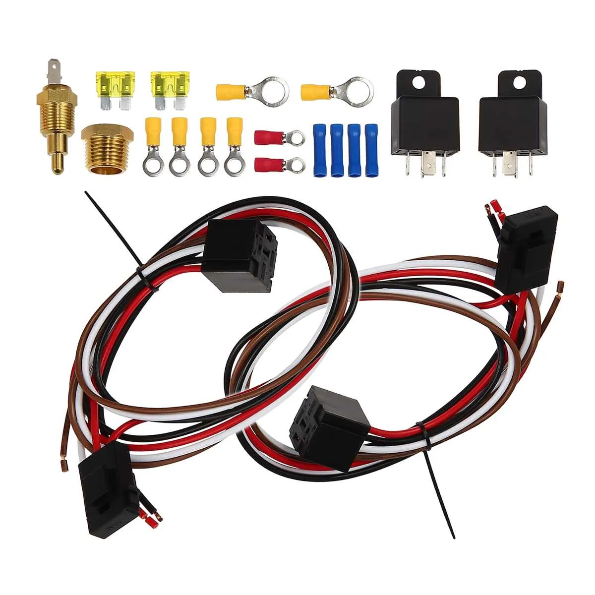
Inspect relay functionality for correct switching. A faulty relay can prevent the units from receiving the necessary signal to turn on. You should hear a distinct click when activating the system, which confirms relay action.
Check for wire shorts or open circuits that may disrupt the system. Inspect the entire length of the cable for visible damage or wear, particularly in areas where friction could cause insulation breakdown.
Verify thermostat operation. If the temperature sensor isn’t providing the correct data, the system may fail to engage. Test the sensor’s resistance at various temperatures to ensure proper function.
Inspect control switches for functionality. A worn-out or faulty switch can fail to signal the correct operation mode. Ensure there is no corrosion or dirt preventing proper contact.
Examine fan motor integrity. A seized or damaged motor will not respond to power. Test the resistance of the motor windings and listen for abnormal sounds that might indicate internal wear or damage.
Check fuses for continuity in the power circuit. A blown fuse can prevent the unit from operating altogether. Replace any fuse that has no continuity to restore power flow.