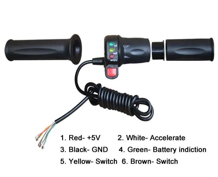
When dealing with the electrical connections for a handlebar control system, it is essential to ensure proper installation to guarantee smooth operation. First, identify the power supply and make sure the wire connections are secure and insulated. The central wire often connects directly to the motor controller and acts as the conduit for signal transmission. Incorrect handling of this component can cause malfunctions or even damage to the system.
Key steps include mapping out the connection points between the handlebar unit, controller, and battery. The red and black wires typically correspond to positive and negative terminals, while the green or yellow wire usually serves as the signal transmission for the control mechanism. When connecting, make sure that all components are aligned in their respective terminals to avoid short circuits or inefficient power flow.
Note: If you’re replacing or upgrading the control system, verify compatibility with the existing wiring layout. Systems vary significantly in design, so a mismatch could lead to functionality issues. For added safety, consider using connectors that are designed to be waterproof, especially for systems exposed to outdoor conditions. Always test the functionality before finalizing the installation.
Wiring Guide for Electric Bicycle Speed Control
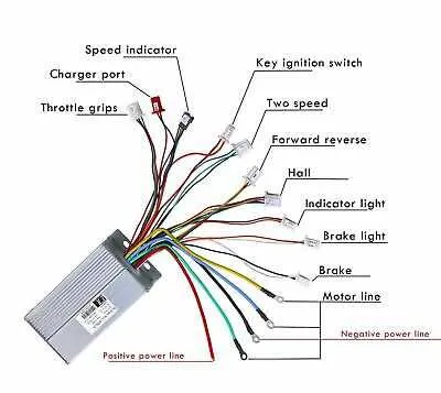
Ensure the connection of the speed control unit by matching the correct terminals. The common configuration consists of three wires: a power wire, a signal wire, and a ground wire. The power wire typically carries 5V or 3.3V depending on the model, while the signal wire sends varying voltage levels that control the motor’s power output based on user input. The ground wire completes the circuit. All wires should be firmly attached to their respective connectors to avoid any interruptions in operation.
For precise functionality, it’s important to connect the signal wire to the controller’s input pin, which usually corresponds to the throttle input terminal. The power wire should connect to the 5V output from the controller. The ground wire needs to be linked to the controller’s common ground point. Verify the wire color codes for your specific setup as they can vary between manufacturers.
When wiring, ensure that no wires are exposed, as this can lead to short circuits. Use proper insulation for safety. Additionally, test the connections with a multimeter before fully assembling the system. After confirming that all wires are properly connected, check the motor’s response to different levels of control input to ensure accurate functionality.
For models using hall effect sensors, the signal wire output will usually be a three-phase pulse, which requires special care during installation. Make sure to correctly align these wires with the motor’s controller to avoid malfunctioning. Always refer to the manufacturer’s documentation for exact pinouts and voltage specifications to avoid damaging sensitive components.
Understanding the Throttle Connection to the Controller
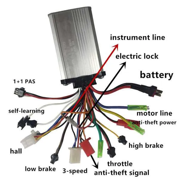
Ensure the correct pinout for the signal cable when connecting the speed control unit to the motor controller. The most common setup involves three wires: one for power, one for ground, and one for the signal. The power wire typically connects to a 5V or 3.3V pin, depending on the specific controller’s requirements. Ground should be connected to the ground terminal, while the signal wire transmits the control input to regulate speed.
Signal wire polarity is crucial–if incorrectly connected, it may lead to erratic motor behavior or failure to respond. Always verify that the signal wire is linked to the controller’s designated input pin.
Throttle testing after connection is essential. Using a multimeter, check the output voltage from the signal wire as you gradually increase input. The controller should register a change in voltage, typically between 0-5V, corresponding to the desired speed range.
When making connections, double-check wire colors to ensure compatibility with the controller’s manual. Each model may vary in color coding, so using a tester or referring to the controller’s schematic helps avoid mistakes.
If you’re experiencing unstable responses, inspect for loose or corroded connectors, and ensure the ground connection is secure. A solid ground is vital for proper signal transmission and safe operation.
How to Troubleshoot Common Throttle Wiring Issues
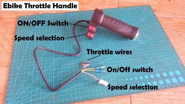
Check for a loose or damaged connection between the controller and the input sensor. Inspect all connectors and wires for wear or breaks. If any of the connectors are corroded, clean them with contact cleaner and reattach firmly.
Test the voltage output of the sensor. A multimeter can be used to measure the voltage changes when the input is manipulated. If there’s no change in the reading, the sensor may be faulty or disconnected from the system.
Inspect the signal wire for shorts. Use the continuity function of a multimeter to check for any unintended connections. A short could cause erratic behavior or complete failure in response to input.
If the unit is unresponsive, check the controller’s settings to ensure they are correctly configured to accept the input device. A reset of the controller may resolve software-related issues.
Check the resistive value of the input sensor, especially if it’s a potentiometer-based system. If the resistance is inconsistent, replace the sensor. The expected resistance values are often listed in the user manual for the device.
If everything seems intact but issues persist, examine the power supply. Low voltage can cause malfunction in the signal response. Verify the battery voltage is within the expected range.
Step-by-Step Guide to Replacing a Faulty Throttle Connection
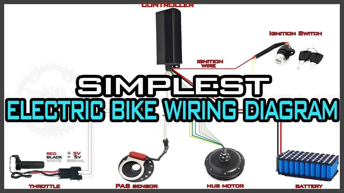
If the power control on your bike is malfunctioning, it’s time to replace the defective component. Here’s a direct guide on how to restore proper functionality.
- Preparation:
- Ensure your bike is turned off and the battery is disconnected.
- Gather necessary tools: wire cutters, a screwdriver, and a soldering iron (if needed).
- Locate the Damaged Part:
- Find the area where the control module is connected to the motor system.
- Look for visible damage such as frayed wires or loose connections.
- Remove the Faulty Connection:
- Loosen the screws or clips holding the damaged part in place.
- Cut away any defective wiring using the wire cutters.
- Install the New Component:
- Place the replacement control part in the correct position.
- If necessary, solder the new connections, ensuring a strong and secure bond.
- Reconnect the Wires:
- Strip the insulation off the wire ends carefully, if required.
- Attach the new wires, matching the correct colors and positions as per the manufacturer’s guide.
- Test the New Component:
- Reattach the battery and power up the bike.
- Test the response of the control to ensure proper functionality.
- Final Check:
- Make sure all connections are tight and secure, and that no wires are exposed.
- Ensure there are no loose parts or exposed metal before riding again.