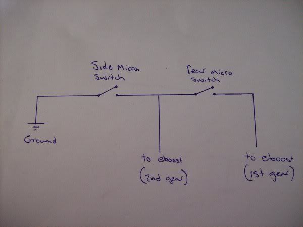
Refer to the following table and diagram for detail on wiring the e-Boost2. Wire. Connect to.
RED. + 12 Volts switched through ignition – connect via 5 Amp fuse.

Refer to the following table and diagram for detail on wiring the e-Boost2. Fuse Holder – 5 amps.
e-Boost2 Quick Start Guide
Basic e-Boost2 Wiring Diagram. Yellow Wire: To – 12V.
Refer to the following table and diagram for detail on wiring the eBoost2. Fuse Holder 5 amps Basic eBoost2 Wiring Diagram 1 before you start important notes.
Refer to the following table and diagram for detail on wiring the e-Boost2. Fuse Holder – 5 amps.
Basic e-Boost2 Wiring Diagram. Yellow Wire: To – 12V.
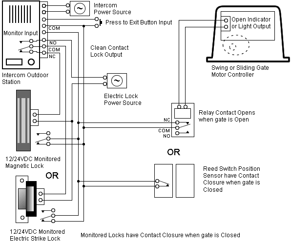
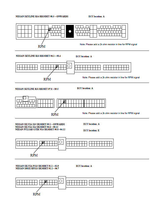
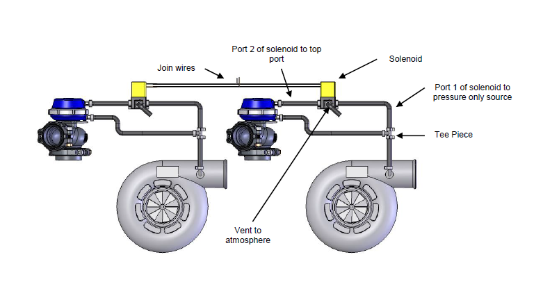
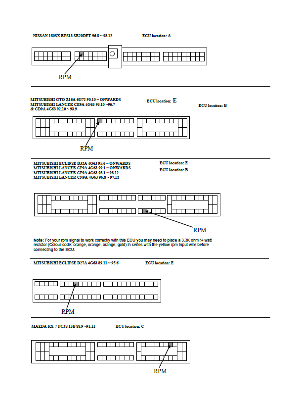
for vehicle specific ECU wiring diagrams as a guide for the RPM signal that plugs directly into the eboost2 LED output with no additional wiring.1 Wiring loom Connect e-Boost2 to vehicle 1 Earth eyelet Connect to wiring loom mm Heat shrink Shield solder joints mm Figure eight wire Connect wiring loom to e-Boost2 solenoid 1 5 Amp fuse Connect to 12 Volts – see wiring diagram 10 Cable ties Secure wiring 1 Panel mounting bracket Secure e-Boost2 to panel. ABS Troubleshooting for Trucks, Trailers, and Buses.
ECU Wiring Diagrams listed by Make and Model. Locate the correct wiring diagram for the ECU and system your vehicle is operating from the information in the tables below.
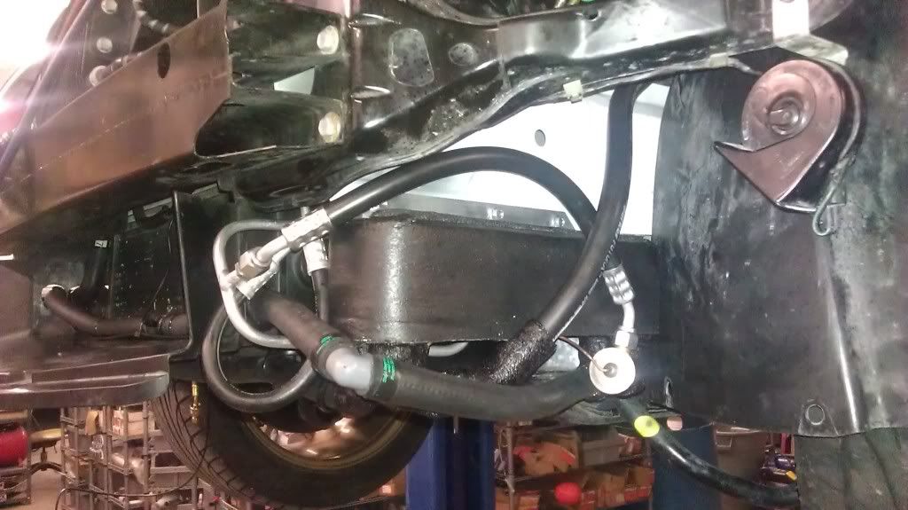
Oct 11, · Yes. Its a Tach Sig wire. I have an output on the FAST that I connect mine to, but you may need to get an Autometer Tach Adapter for a Mod Mustang to get the correct signal.
Solenoid, Wiring Loom, and Hoses and Hose Fitting Kit. e-Boost2 allows the user to control, monitor, map and compensate boost. But e-Boost2 is a lot more than just a boost controller – it can also control water spray, methanol or nitrous injection, manage shift/warning lights and read/monitor RPM.
– Refer to the following table and diagram for detail on wiring the e-Boost2. Wire Connect to RED + 12 Volts switched through ignition – connect via 5 Amp fuse supplied.Wiring Failsafe Controller Cut [Archive] – schematron.orgeBoost2 60mm Black
