Wiring diagrams are common for all . for remote wiring connections.
.. side of these limits, please consult EIM to ensure that actuator performance.
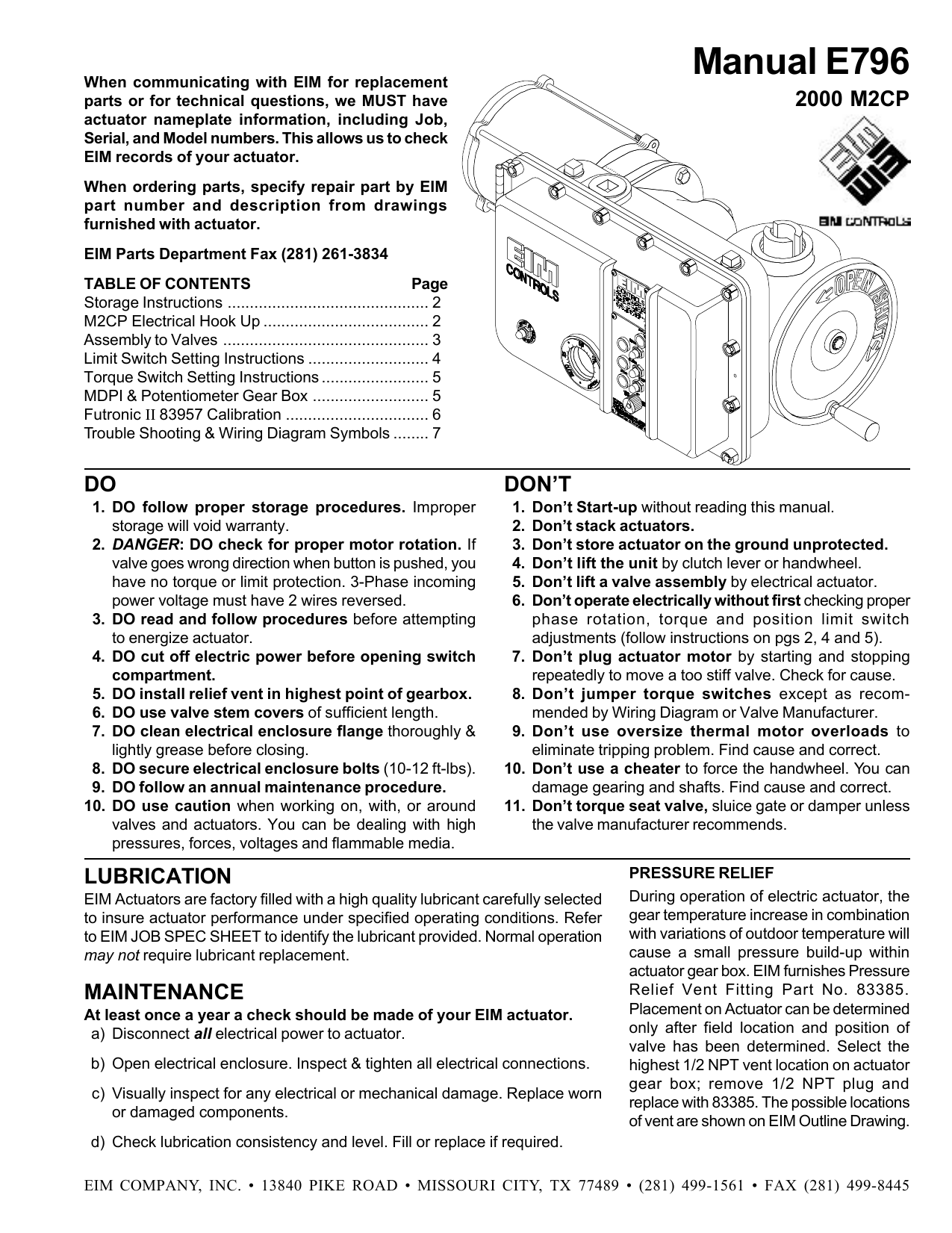
Section 4: Geared Rotary Limit Switch Setting Instructions. Before . At least once a year a check should be made of your EIM actuator.
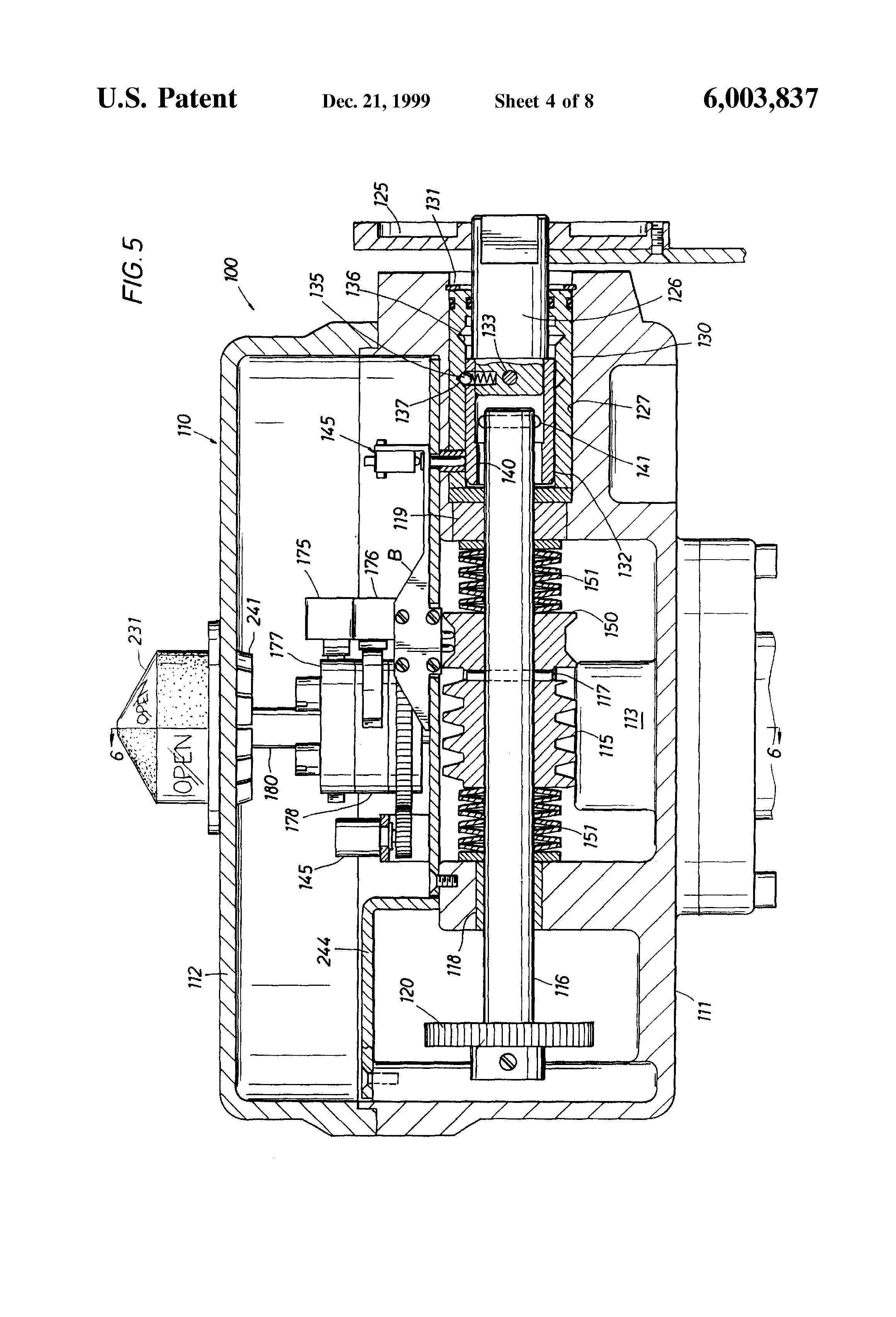
a. WARNING: Failure to follow instructions for proper electrical wiring, EIM TEC Series Actuators have been designed and manufactured to provide. 2) O Customer wires to terminals on PWR and TBM modules.
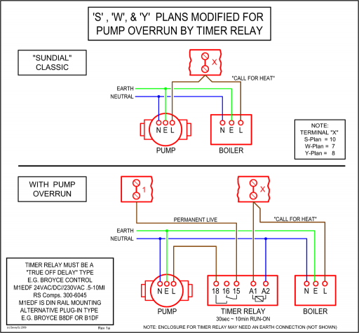
O M2CP Internal terminal interconnect wiring points. wiring to valve actuator.
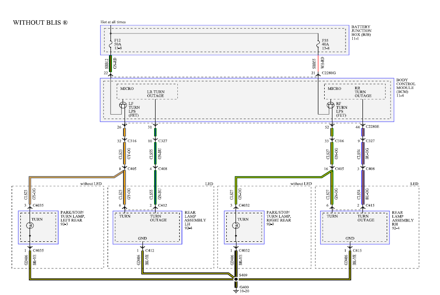
DIAGRAM. EIM™ is a recognized brand leader from Emerson – Actuation Technologies.
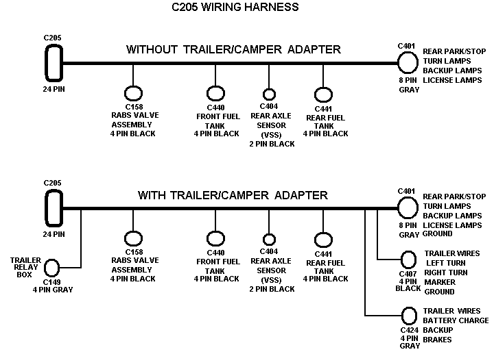
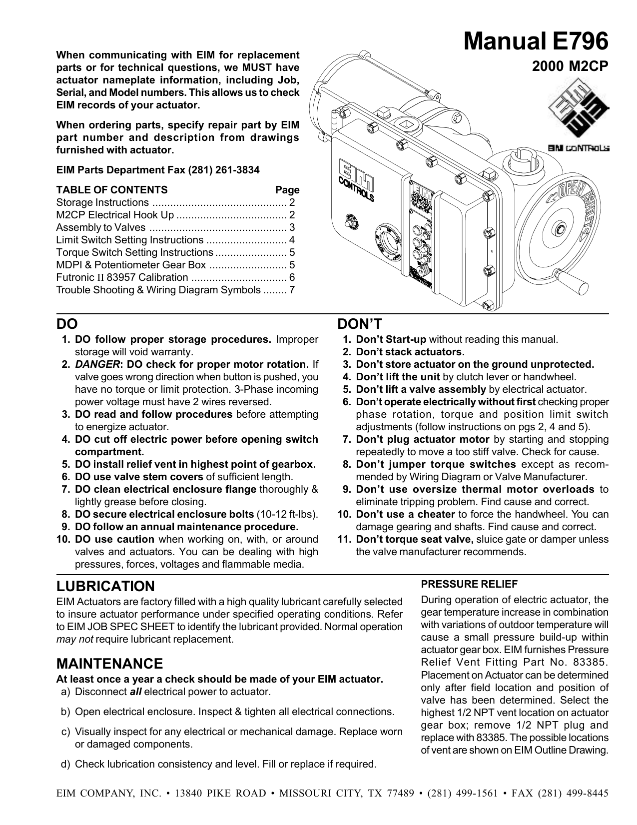
The EIM In addition, EIM actuators and controls have established wiring cost.Remove PWR and TBM covers to expose terminals for customer wiring. EIM Modular Modular Control Package (M2CP) is available configured in many combinations of electrical and electronic parts.
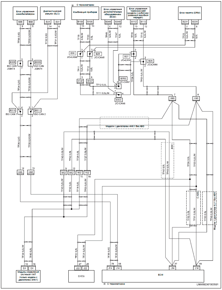
Refer to WIRING DIAGRAM and EIM JOB SPEC SHEET for components provided by EIM. Connect control wires to TBM and Power (motor) Voltage to PWR terminals.
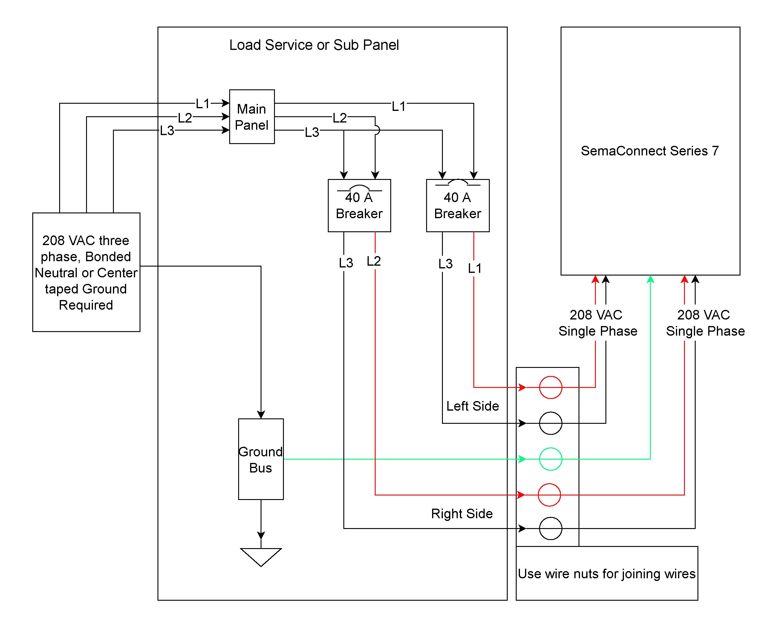
Actuator Wiring Diagrams Direct Coupled Actuators – Spring Return Models. Direct Coupled Actuators – Spring Return Models Wiring for (0) Vdc proportioning controller operating multiple actuators Wiring for 3 kOhm Economizer controllers M 3KΩ 0°° OR + 90°-0° OR N/A. View and Download Emerson EIM Series installation and maintenance manual online.
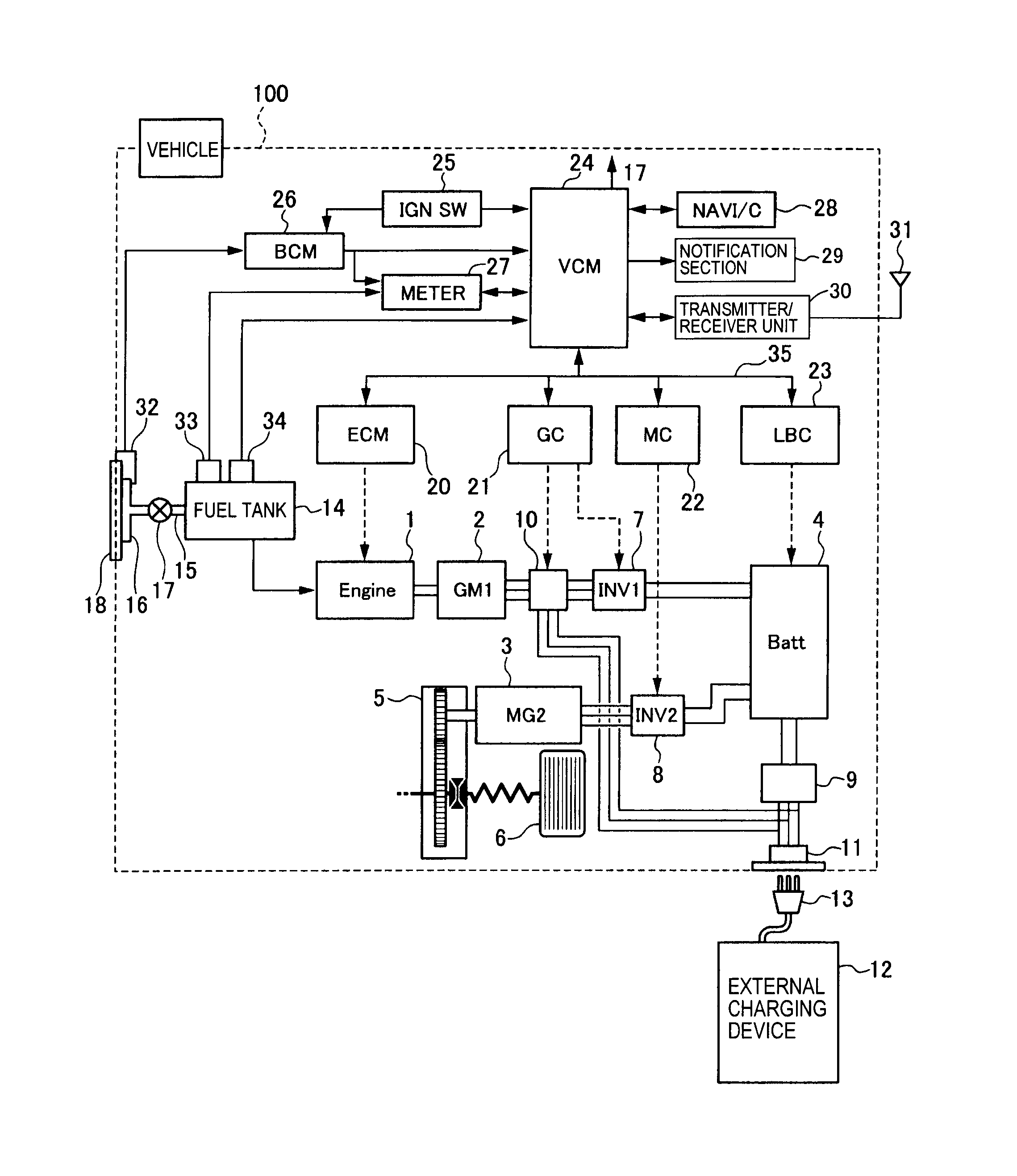
E MCP. EIM Series Controller pdf manual download.
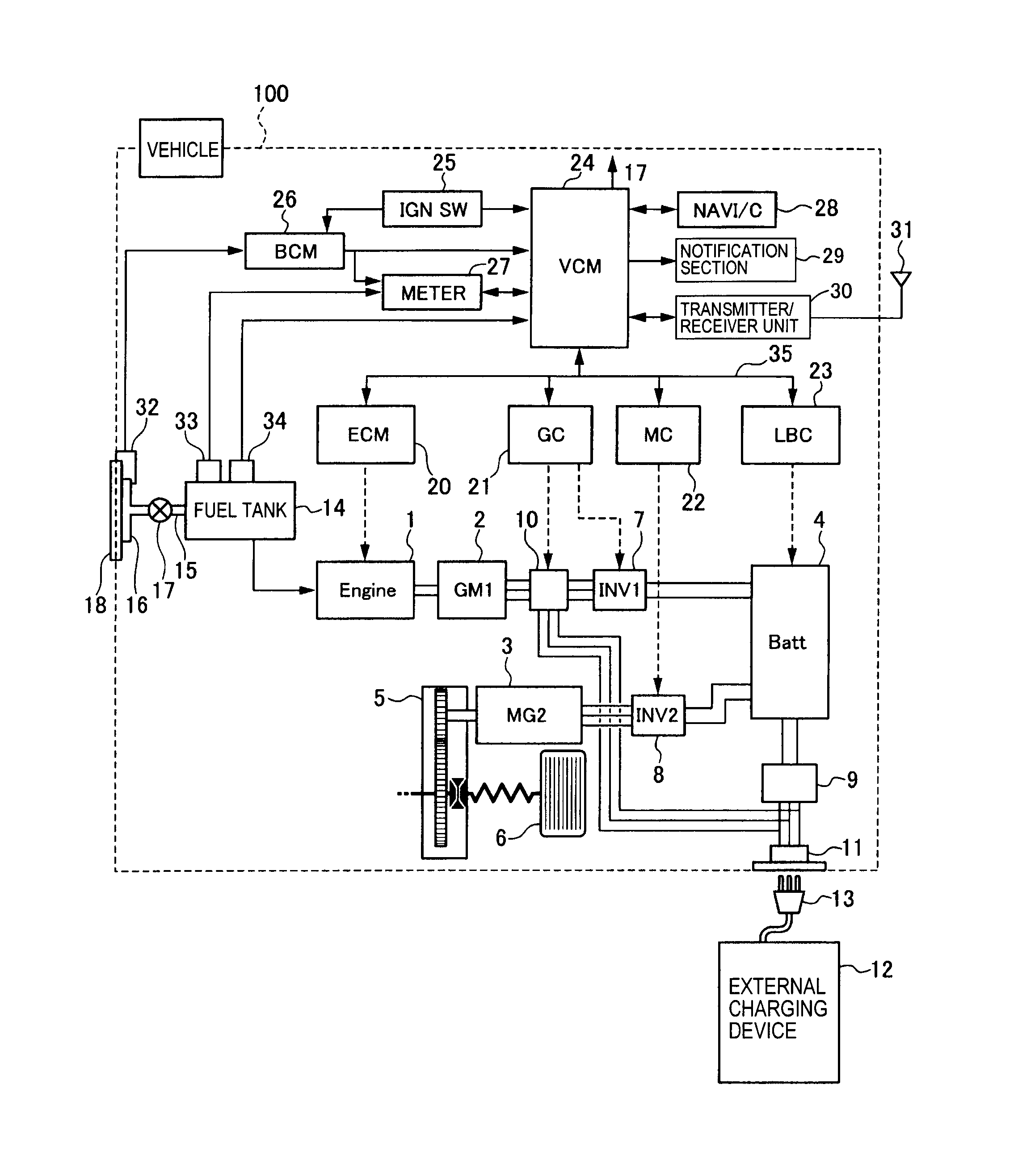
Emerson EIM Series Installation And Maintenance Manual. Wiring Diagram Symbols for MCP Figure 16 Potentiometer 1K OHM CLOSE Pot. Slider is geared to Valve Position and “In-step” at all.
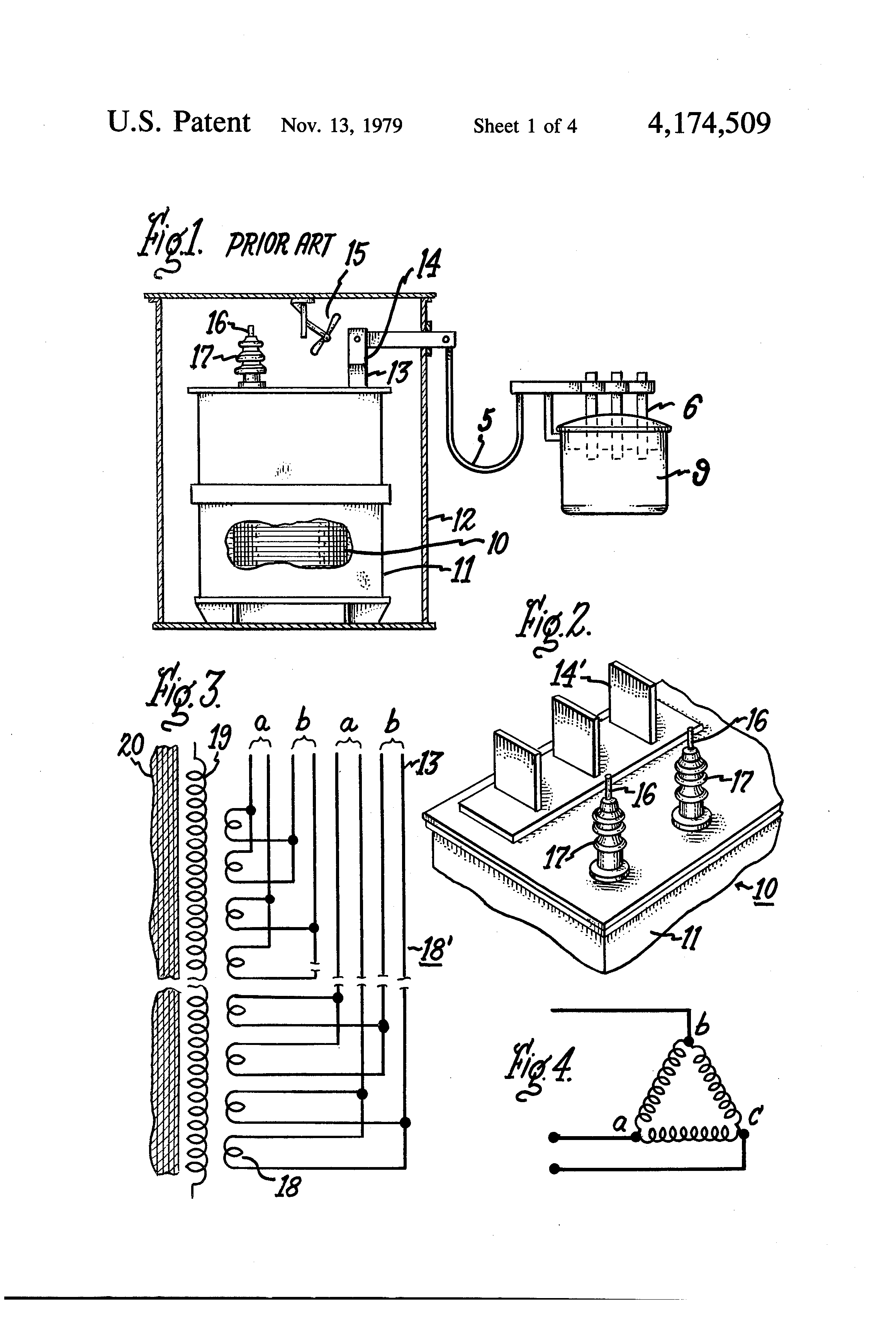
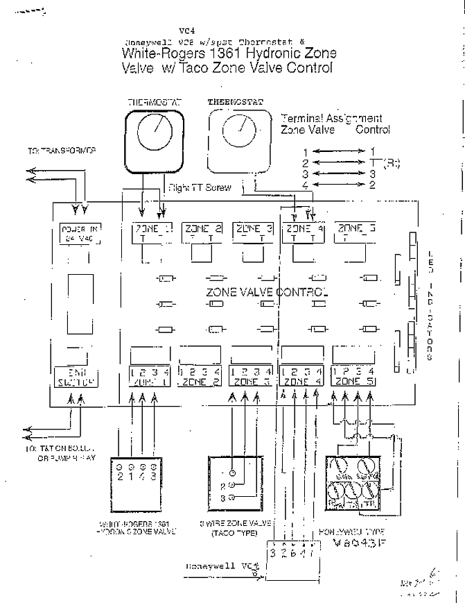
Eim Valve Wiring Diagram – Electrical wiring diagrams Eim Actuator Wiring Diagram Trusted Wiring Diagram Honeywell Thermostat Wiring Diagram Eim Valve Wiring Diagram. Nordstrom Wiring Diagrams – Daily Update Wiring Diagram • limitorque wiring diagram just another wiring data rh allwiring today.
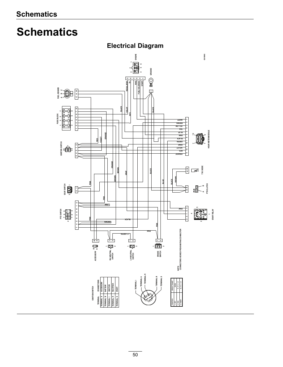
What Every Body Is Saying About Eim Actuator Wiring Diagram Is Wrong and Why. Your generator overspeed setpoint is currently calibrated! For instance, the diagram should demonstrate the right direction in the constructive and negative terminals of each component.Valve Actuator Wiring Diagram | Wiring LibraryWiring Diagrams Model Eim Valve Actuators.
Wiring. Automotive Wiring Diagrams
