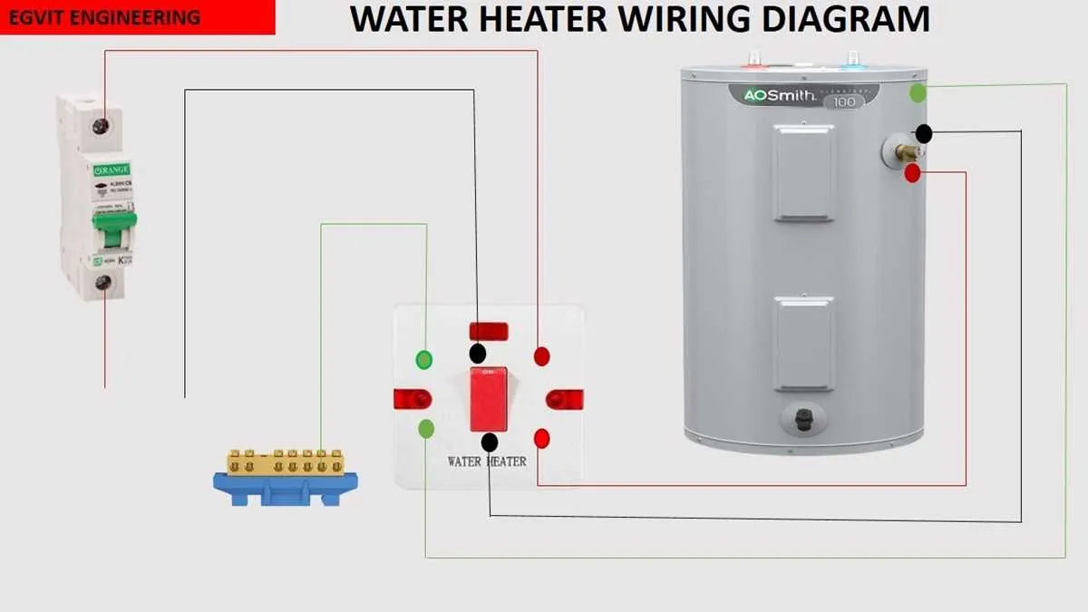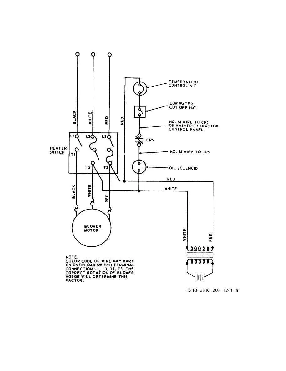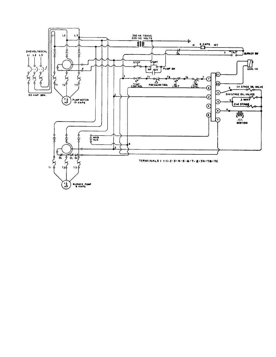
To ensure safe operation and prevent electrical faults, use a dedicated circuit breaker rated at 20A for this type of appliance. The supply cables must have a minimum cross-section of 2.5 mm² copper wire, suitable for continuous current flow without overheating.
Integrate a residual current device (RCD) with a sensitivity of 30 mA to reduce the risk of electric shock. The control switch should be rated for at least 250V and 16A, positioned close to the unit for quick disconnection in emergencies.
Correct polarity is crucial: the live conductor must connect to the terminal marked for line input, while the neutral wire goes to the corresponding neutral terminal. Grounding is mandatory to avoid potential hazards from insulation failure; connect the earth wire to the grounding terminal with a secure clamp.
Follow manufacturer specifications strictly when installing the internal elements. Verify all connections with a multimeter before powering up to confirm continuity and absence of short circuits. Use heat-resistant connectors and avoid splicing cables outside junction boxes.
How to connect a heating device to a standard household circuit

Begin by ensuring the power supply is switched off at the breaker panel. Use a dedicated 15-amp circuit if the appliance power rating does not exceed 1800 watts; otherwise, opt for a 20-amp line. Employ copper conductors with appropriate insulation rated for at least 75°C. The live wire must connect to the device’s input terminal marked L, the neutral conductor to N, and the protective earth to the grounding terminal.
Install a double-pole switch or a circuit breaker with a residual current device (RCD) for safety. This setup reduces the risk of electrical shock and prevents overloads. Use junction boxes with secure connectors to maintain solid contacts and avoid loose connections.
For wall-mounted units, route the cables through conduit to protect against mechanical damage. Confirm the cable cross-section matches the current load–1.5 mm² for up to 15 amps, 2.5 mm² for higher demands. After connecting, test the circuit with a multimeter to verify correct polarity and continuity before restoring power.
Wiring Safety Tips and Common Mistakes to Avoid
Always disconnect power at the circuit breaker before starting installation to prevent electrical shock. Use a voltage tester to confirm the absence of current.
Choose cables rated for the correct amperage and temperature specific to the device’s specifications. Undersized conductors can cause overheating and fire hazards.
Ensure all connections are tight and secure with proper terminal screws or connectors. Loose contacts increase resistance and lead to potential failure or sparking.
Do not splice wires inside the device enclosure unless the manufacturer explicitly allows it. If splicing is necessary, use an approved junction box with strain relief.
Follow color-coding conventions strictly: typically, black or red for live, white for neutral, and green or bare copper for ground. Misidentification risks malfunction and injury.
Avoid overloading the circuit by confirming the total load does not exceed the breaker’s rating. Use a dedicated line if required by code or device rating.
Inspect insulation carefully for nicks or cuts before installation. Damaged sheathing compromises safety and can lead to shorts or shocks.
Use a ground fault circuit interrupter (GFCI) or residual current device (RCD) in damp or wet locations to enhance protection against electric shock.
Common errors include reversing neutral and ground wires, failing to connect the grounding conductor, and neglecting to use strain reliefs on flexible cords.
Always follow the manufacturer’s installation guide precisely and comply with local electrical codes and regulations to ensure safe operation.
Step-by-step guide to troubleshooting wiring issues in electric heaters

Begin by disconnecting the device from the power supply to avoid electrical hazards. Use a multimeter to check continuity across the main connections, ensuring no open circuits are present. Inspect terminals for corrosion, loose screws, or burnt marks; tighten or clean as necessary.
Test the power cord for breaks or frayed insulation by visually inspecting along its entire length. Measure resistance to confirm the integrity of internal conductors. Replace the cord immediately if any damage is detected.
Examine the internal junction box where cables converge. Verify that all wire nuts or connectors are secure and that no strands are exposed. Confirm that grounding wires are properly attached to the chassis.
Check the thermostat leads for continuity; a faulty sensor can cause the device to malfunction. If readings are inconsistent, replace the thermostat component. Additionally, test the heating element by measuring resistance; a value significantly outside the manufacturer’s specifications indicates a broken filament.
Look for signs of overheating such as melted insulation or discoloration near connectors. If overheating is identified, investigate the cause–usually loose connections or overcurrent conditions–and repair or replace damaged parts accordingly.
After completing inspections and repairs, reassemble all components carefully and restore power. Monitor the unit for proper operation and absence of unusual noises or smells. Repeat testing if problems persist to isolate less obvious faults.