Changes in routing may require a change in the wire used to cabinets or Single Conductors (Power & Lighting) (Size as shown in plan, IMSA.
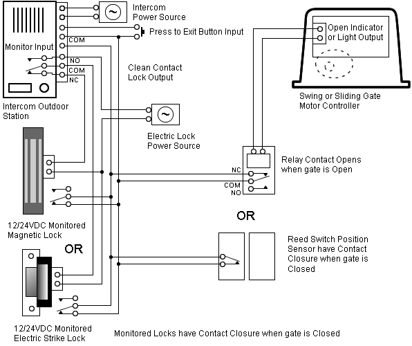
). All the connections are designed according to our best expertise and have Eaton Wiring Manual 06/ 00 ..
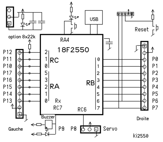
product and save it as a PDF document or . refer to the wiring diagrams at the end of this. Chapter.
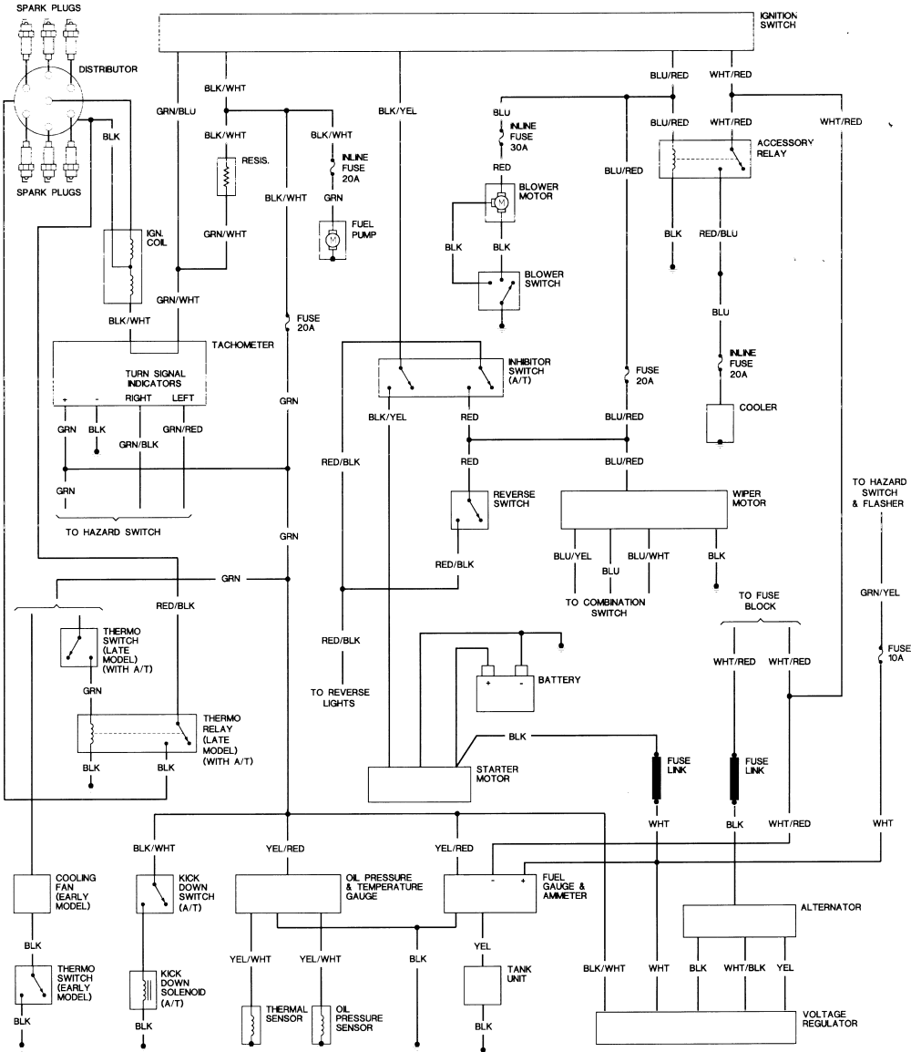
2 Before tackling any troublesome electrical circuit, first study the wiring diagram (see end of Chapter). ACC. Illumination.
Circuit. 1) CONTENTS OF ELECTRIC WIRING DIAGRAM ( CIRCUIT).
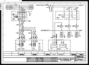
POSITION. EXPLANATION.
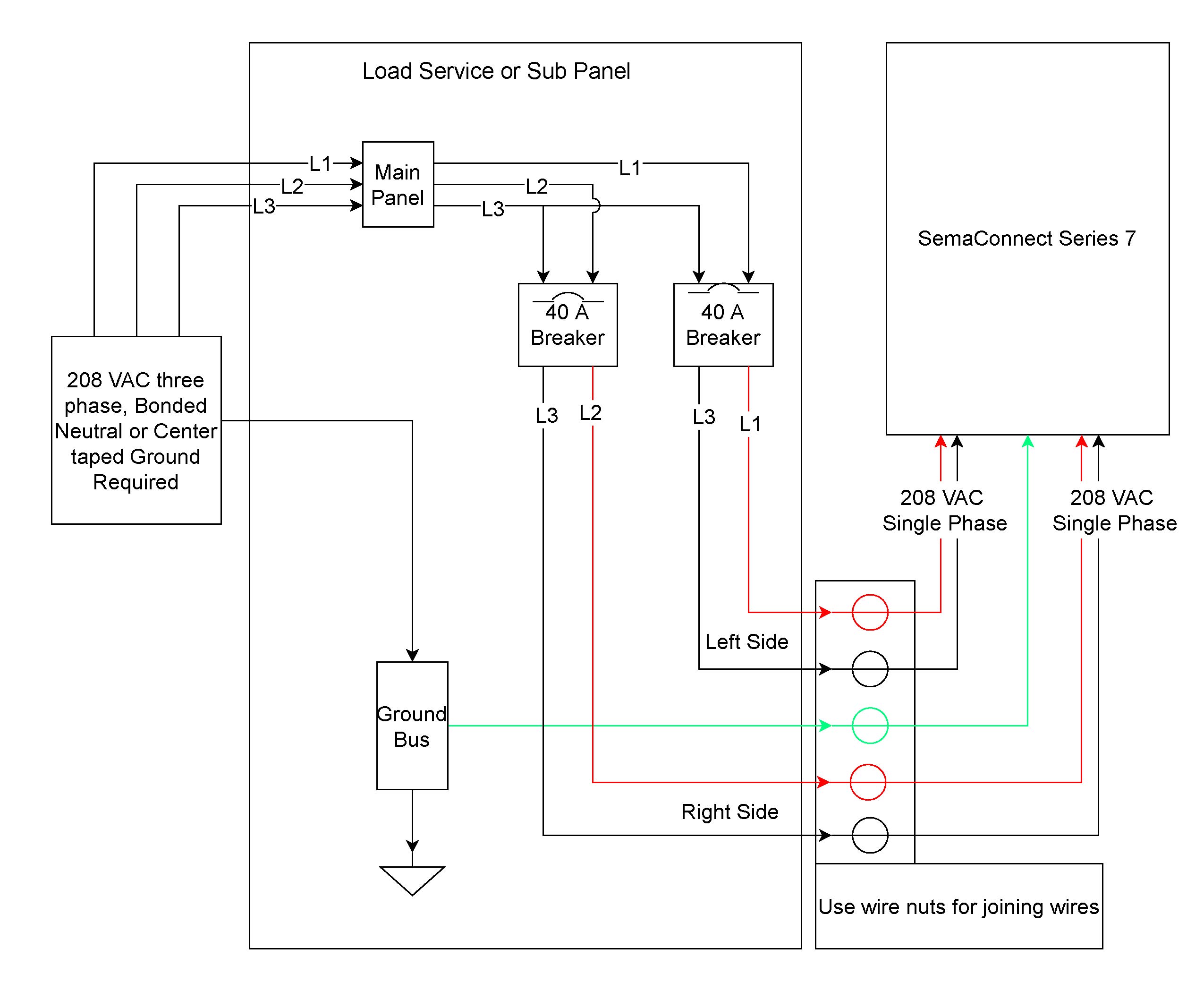
– Upper horizontal lines: Power supply lines. CIRCUIT DRAWINGS AND WIRING DIAGRAMS.
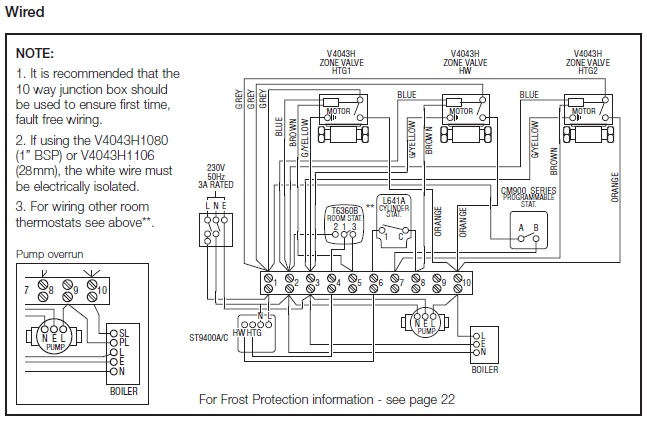
Description. Successfully performing electrical work requires the ability to read and interpret many different.WIRING NOTES: This is a polarity sensitive system.
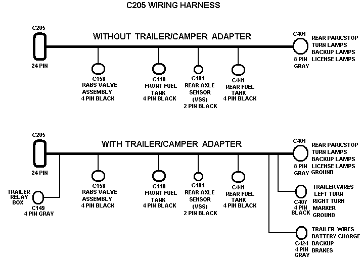
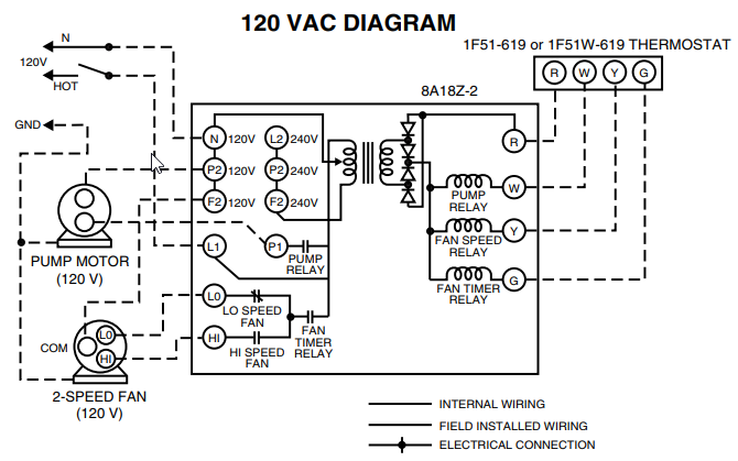
Ensure you wire it exactly as shown in the diagram above. Thermopile wires must also be located with Red at TH/TP and White at TP on the gas valve.
Ge Refrigerator Wiring Diagrams
Millivolt Gas Valve Wiring Diagram Fan Hot (Black) Fan Netural (White) Electronic Fan Speed Control HI MH ML LO OFF FAN SPEED TEST FAN TURNS ON TO. field power wiring marked terminal plug and receptacle schematic diagram single supply circuit yel blu blk relay 3 22 vdc coil t d r relay 2 22 vdc coil t d r brn brn gry red htr6 blu 8 ls6 yel 6 blu ls5 htr5 blk 2 relay 3 htr4 blk 8 ls4 6 htr3 blu 4 ls3 2 relay 2 blk htr2 blk 8 yel yel .
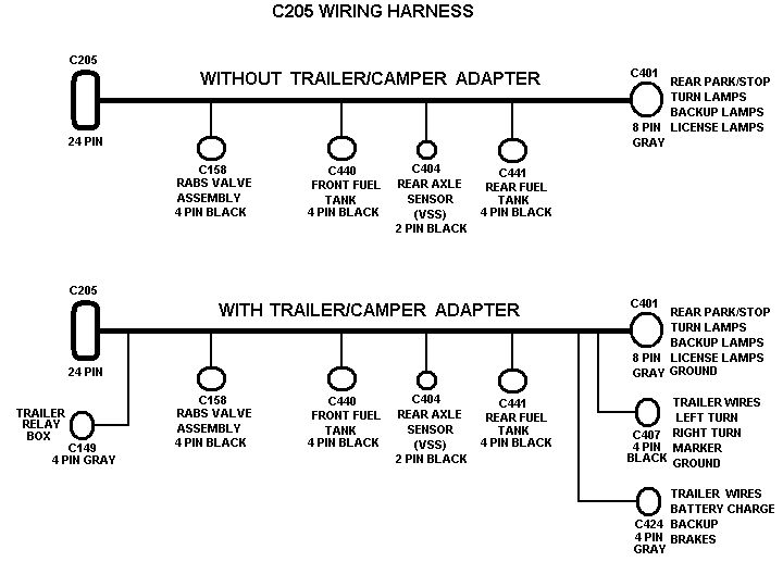
TPD E.8mm 2) All other circuits 5 AMP 16 AWG Chassis harness connector 6 Manual synchronised load sharing APS input (PIN 8) is active RPS input (PIN 30) is inactive Interface harness (if used) See note 5 Main power rly 1 Wiring diagram. 1mm 2) Ignition and 5/5(10).
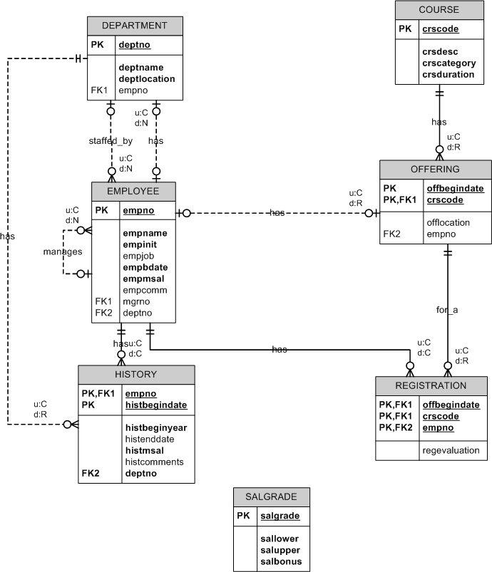
wiring color code yellow-black stripe 19 thru blue-red stripe black-red stripe a black-green stripe represents (am) connection (comet) • splice light . SOURCE: need a wireing diagram for.
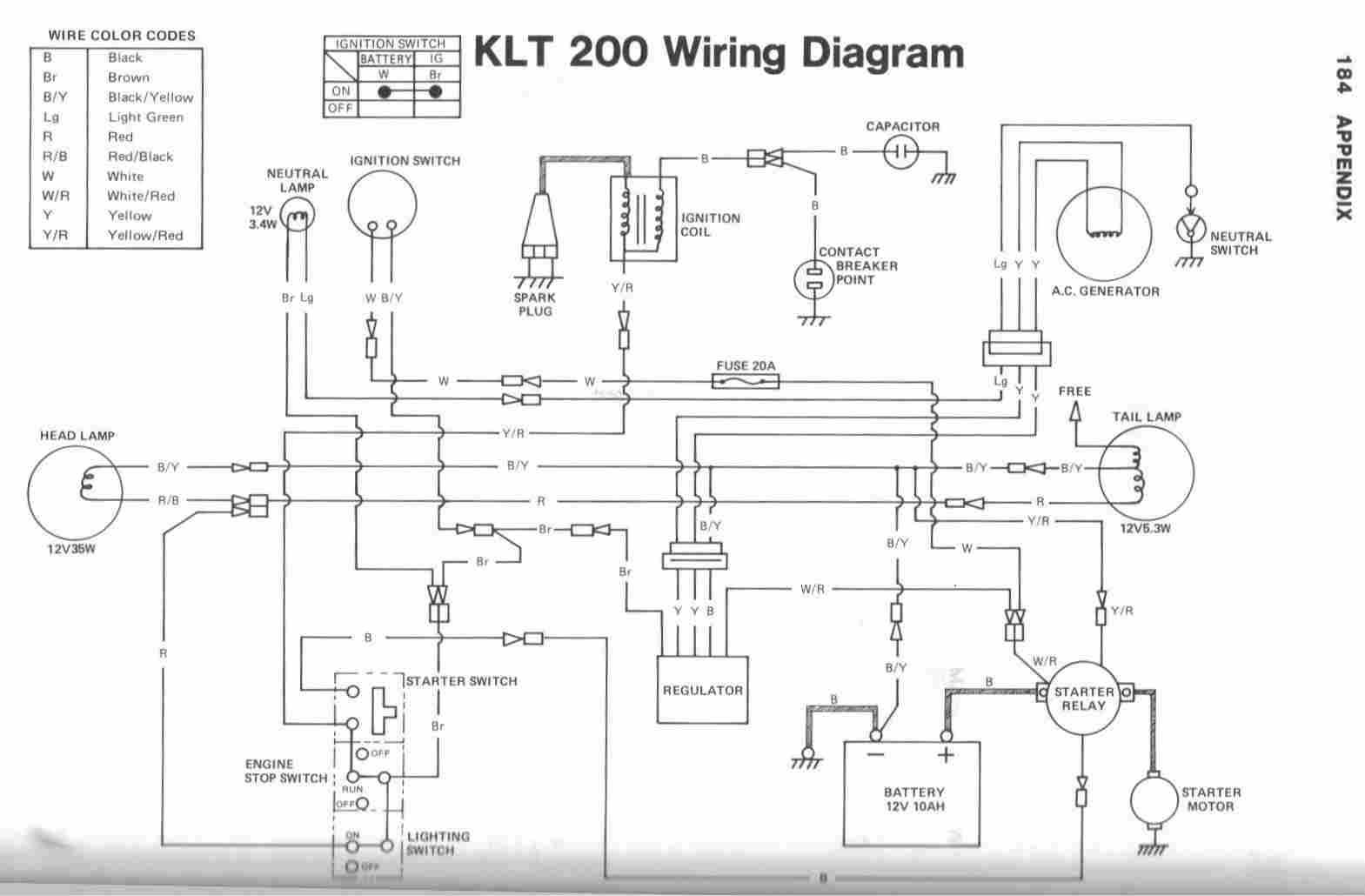
Hi, Often the wiring diagram maybe found in the console area or under the dryer top panel. Due to regional differences in electrical code and power requirement, wiring system hence the diagram may differ.
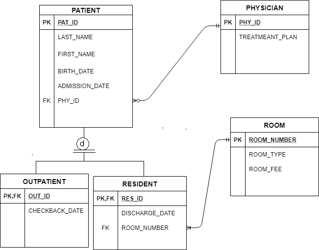
Additionally, it would also differ if .House Wiring for Beginners – DIYWikif wiring diagram | eBay