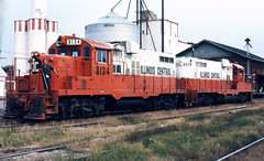
, Plans, end of double track sign C&S (4/30), DS13, , Plans, End of . , Plow installation directive (10/34), BB38, , Pluma, SD , Presentation drawings / color and lettering diagram SD-9 Chinese red, BB48, 95+ , Ship W B Duncan steam ferry Paducah-Metropolis, BB35, The EMD GP10 is a road switcher diesel-electric locomotive that is the result of rebuilding a Nine Alaska Railroad GP7s were rebuilt to GP10s by Paducah.
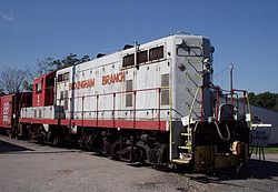
The GP9 rebuilding program by Boise was engine and electrical gear only with no. Our GP-7 is portraying these Soo Line locomotives which called at Osceola.
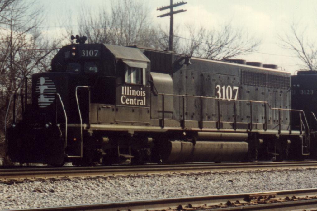
” Enginemen’s Operators Manual – Model GP7 – Aug ’51 Edition,” by EMD; data. Silvis, Illinois shops, or PNC in the Illinois Central Gulf’s Paducah, Kentucky shops.
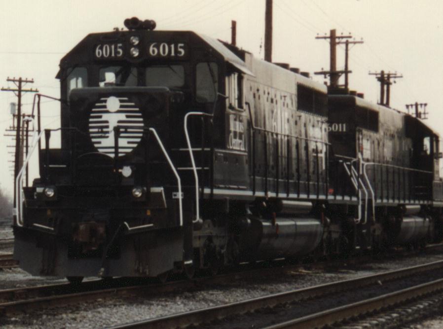
.. Of the original 12 C&S built SD9s , 10 were still shown as. EMD used the field loop system for controlling the dynamic brakes.
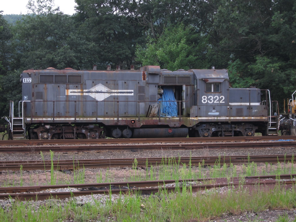
controller, field loop amps vary from zero to fourteen (14) amps plus or minus 10%. . The manual states that “GP and GP units which are not equipped with ..
New York, Susquehanna & Western – Past and Present, Paducah and. 53; IC Railroad diesel diagrams, pp–47; NP Railway diesel diagram .
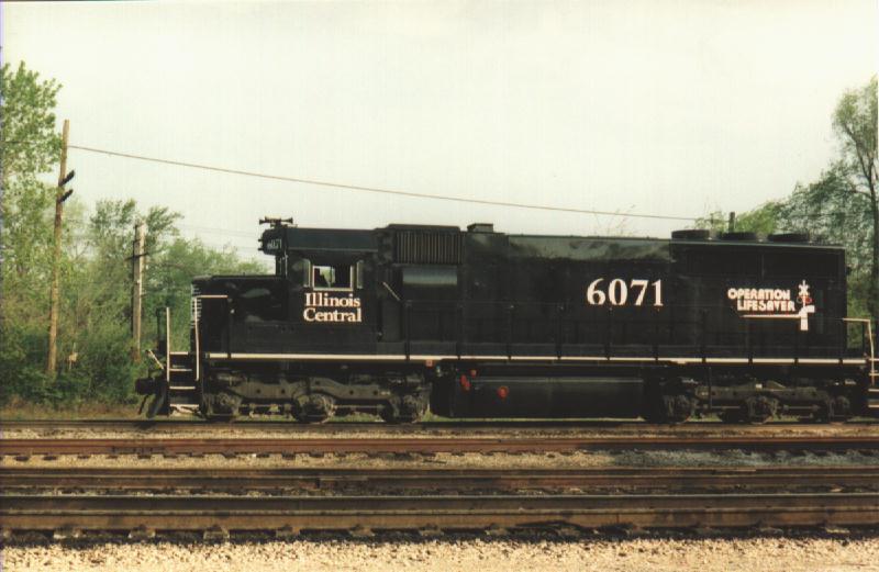
The EMD GP10 is a diesel-electric locomotive that is the result of rebuilding a GP7, GP9 or GP Nine Alaska Railroad GP7s were rebuilt to GP10s by Paducah. The engine’s on-board microprocessors replaced hundreds of wiring circuits.Transition is the process by which the transmission of a diesel-electric locomoitve is brought from series wiring to parallel wiring.
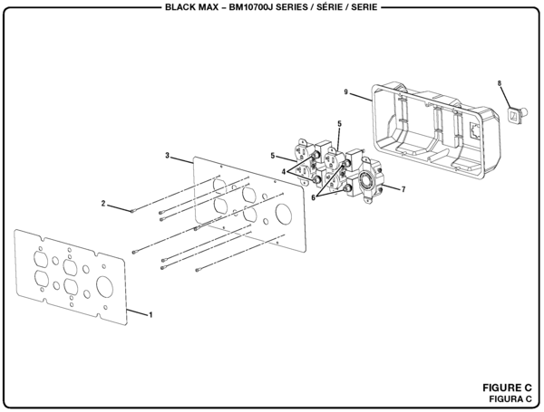
When in series, all current in the locomotive pass through all motors: this produces maximum low-speed force in the motors, i.e., maximum starting torque. I looking train begins the trip out of Waterloo bound for Council Bluffs.
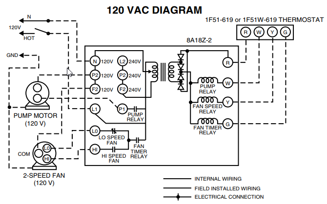
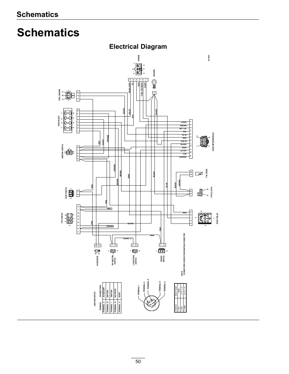
The train passes thru Susie on the west end of double track at Waterloo. 3 IC 38’s help out this aged Paducah. Jul 24, · As the Subject suggests, I’m interested in a wiring diagram for a GP9. I’ve seen the one in the back of the Operating Manual, but that one isn’t detailed enough.
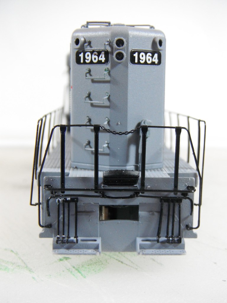
I’d like to have one which will tell me where the wires go, from the terminal block, within the base of the Control Stand. We have the former Norfolk & Western # Cab wiring Main control circuit board and switches XR1 Smoke regulator circuit board X Pick-up shoe power cable wires (2) Smoke unit XR1 Rear circuit board & wiring Engine chassis Motor power feed cable wires NON FAN DRIVEN SMOKE UNIT DIAGRAM DETAIL Locomotive Electrical.
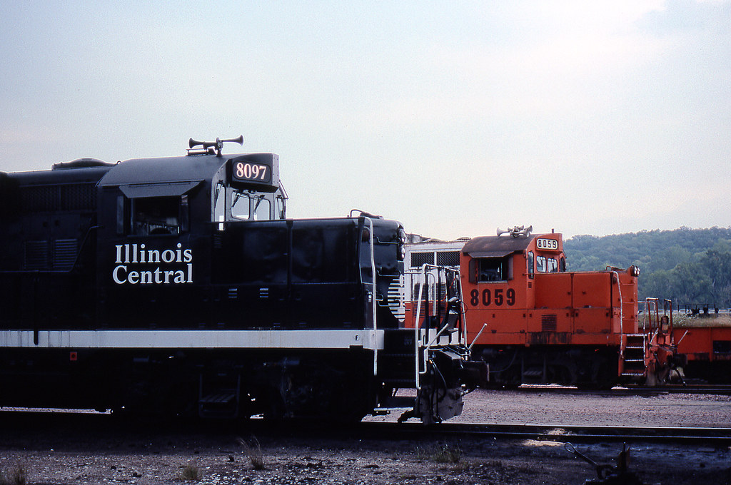
EMD-GP38 Static Excitation Locomotive Maintenance-Electrical Objective:Learn the description of the electrical transmission and the power control system used on the GP38 locomotive for static control of main generator excitation.GP16 – WikipediaUSA TRAINS EMD GP7 ASSEMBLY & DISASSEMBLY INSTRUCTIONS Pdf Download.