can be used, for example, to diagnose a short-circuit at the output. Each output on the for short circuit).
• Direct control of the outputs via ems 4 input module. They are designed for installation in the control cabinet (DIN rail).
via sliding switches on the device (see connection diagram). Working current principle.
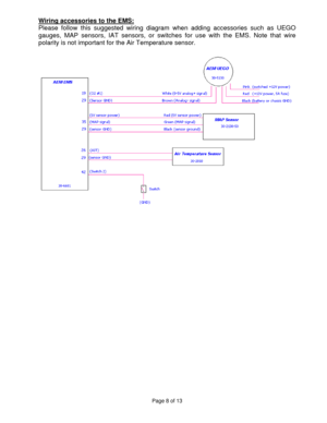
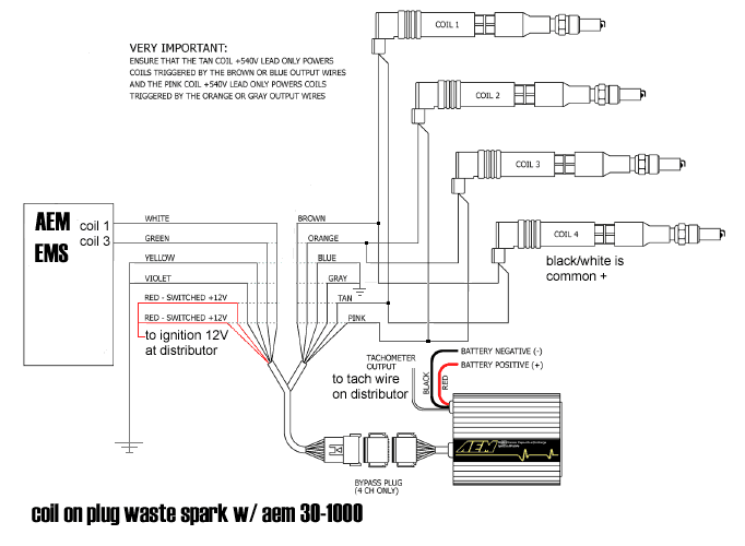
Aem ems 4 wiring diagram. Aem ems 4 wiring diagram.
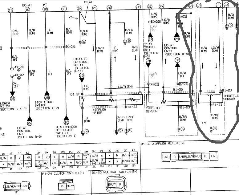
Source: EMSPublished on Print Friendly, PDF & Email. Keep in mind that the EMS-4 is not for everyone.
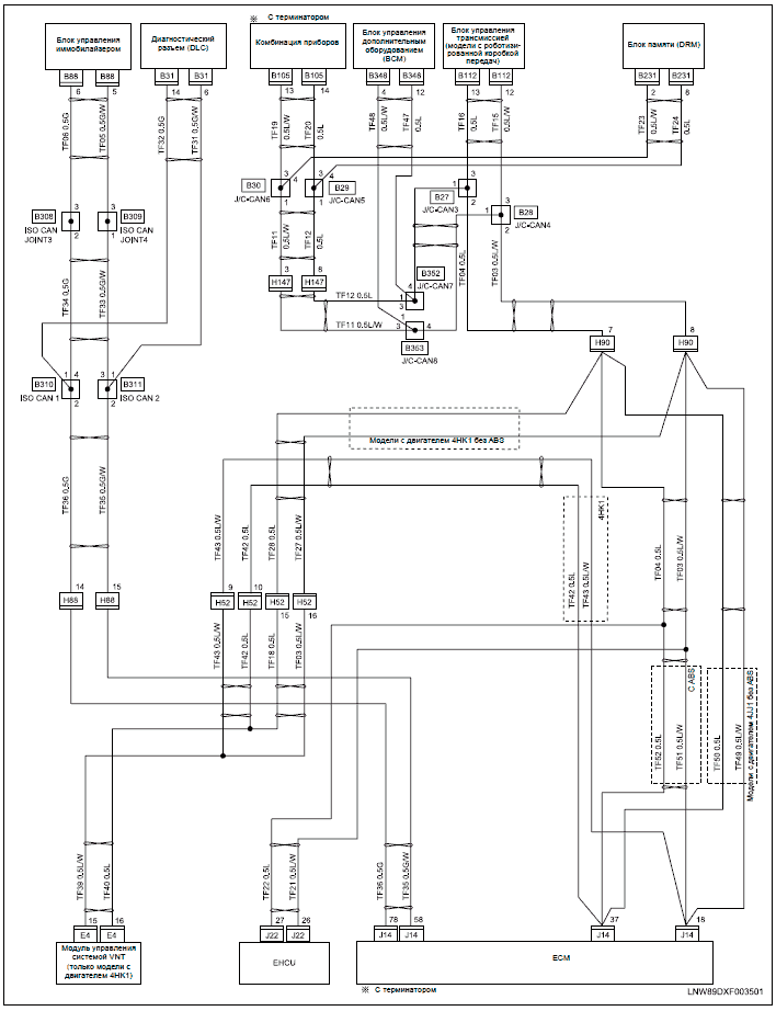
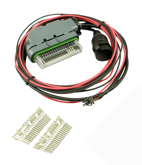
Being a universal system, it must be custom wired either using the EMS-4 full universal. AEM EMS These are harnesses for the use of AEM’s EMS The EMS-4 has full control of fuel and ignition timing. Some vehicles may need an aftermarket.A wiring diagram is a simple visual representation of the physical connections and physical layout of an electrical system or circuit.
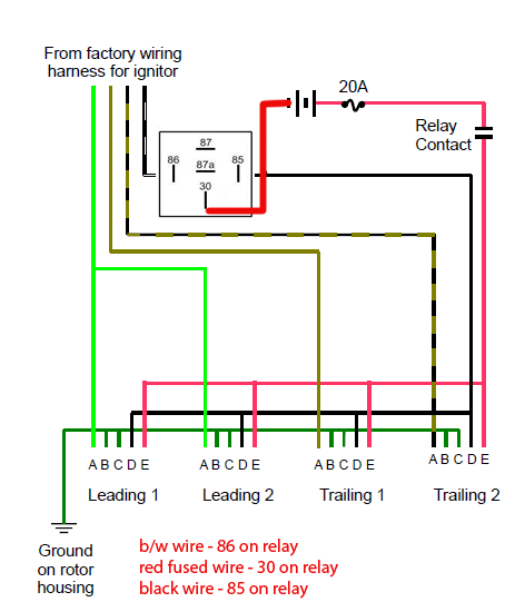
It shows how the electrical wires are interconnected and can also show where fixtures and components may be connected to the system. Getting Started When you start the Stinger 4 ECU Control Software the first screen to appear is the tuning screen.
You can read data from the ECU or a saved file by selecting the appropriate menu option. Ems Stinger Wiring Diagram micro manual pdf gonsdehisroles micro manual pdf manuals for mega 2 micro ms2 diypnp mspnp2 and mega 2 setting up manual pdf mega 2 mise en route fr pdf..

So ideas if you desire to receive all of these wonderful images regarding Ems Stinger Wiring Diagram, simply click save button to store these shots to your pc. Check out how we install an AEM EMS-4 in this Project Car. – Project Car Magazine When it comes to plug-and-play engine management systems, AEM has led the way with its .
EMS Installation Part 3 – Wiring and fitting EMS unit
4) Wiring Accessories to the EMS: Please follow this suggested wiring diagram when adding accessories such as UEGO gauges, MAP sensors, IAT sensors, or switches for use with the EMS. Signals marked ‘tapped’ should be spliced onto the existing wire without disconnecting the original circuit.Srt 4 Dlc Wiring Diagram | Wiring LibraryEms Stinger Wiring Diagram – schematron.org
