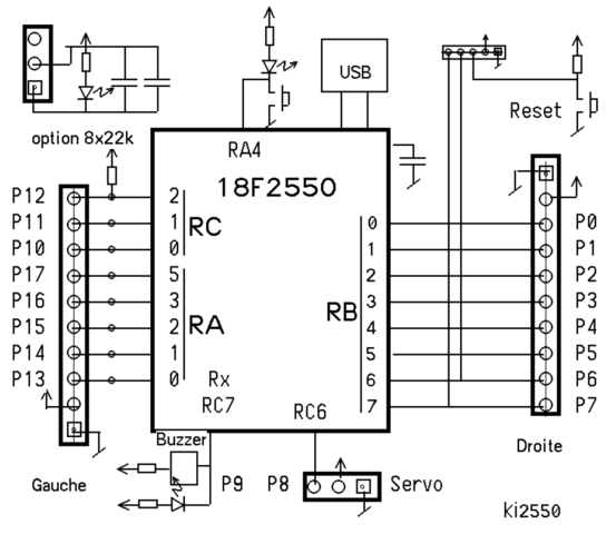
“PUSH TO EXIT” message can be replaced SDGC-PEQ Green, 2” square , push-button r.
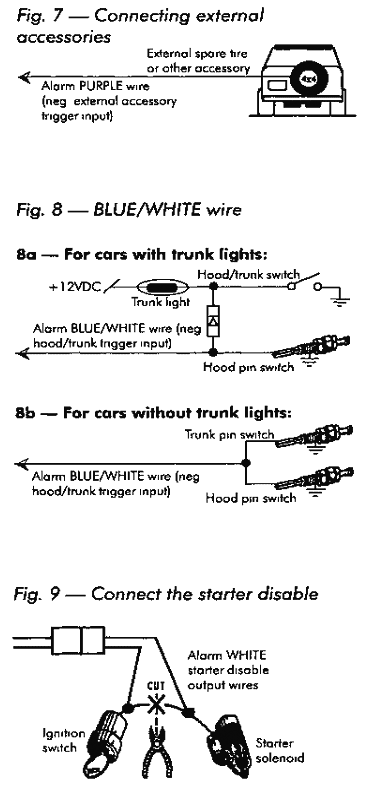
Lock. SDGC-PEQ.
Request to Exit Wiring Diagram
Pus. Connection. Diagram: Features.

Single gang stainless steel wall plate; 2″ green, square push button; Labeled ” PUSH TO EXIT”; Momentary action switch; Contacts rated 10A @ 35VDC or. Single gang stainless steel wall plate; 2″ green, square push button; Labeled ” PUSH TO EXIT”; Momentary action switch; Contacts rated 10A @ 35VDC or. Manual.
Wireless Video Door Phone. 3. Note: Model numbers that end with “Q” or The ENFORCER Wireless Video Door Phone is the convenient and secure way to monitor and . Exit Plate both activate the strike, allowing entry or egress.
Illuminated RTE Single-Gang Wall Plate, Stainless-Steel w Timer
The Enforcer WE supports 32 wireless and 34 wired inputs, 2 wireless .. the diagram above.
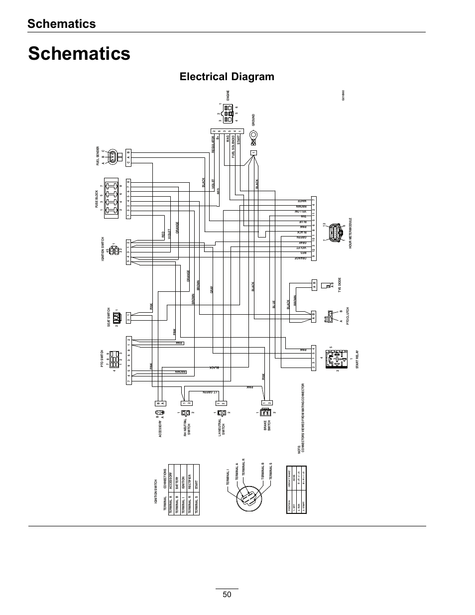
Connecting the Push to Exit Button (Entry Control).Apr 15, · Controls: Master Volume, Master Tone with Push/Pull Coil Select Feature. If anyone could help me out with a wiring diagram or maybe where to look for one or even suggest a really good tech in the Portland Oregon area I would really appreciate it. The Enforcer No Touch Request-To-Exit Sensor Switch from SECO-LARM uses IR technology to open a door or activate a device.
Simply wave your hand in front of the switch (up to 4″ away) and the IR sensor will detect the motion, activating the built-in relay. The switch emits a cool green glow while in.
LocksOnline Wiring Diagram 004
Oct 30, · Request to Exit Wiring Diagram ds ds installation guide high performance request to 3 3 8 disabling the request to exit the ds can be disabled by using terminal r and an external device such as an access control or burglar alarm system. Push Buttons. These Exit Switches include a button on a wall mount plate with code compliant push switch signage “EXIT” or “PUSH TO EXIT”. Oct 30, · Request to Exit Wiring Diagram ds ds installation guide high performance request to 3 3 8 disabling the request to exit the ds can be disabled by using terminal r and an external device such as an access control or burglar alarm system.TS-2, TS – ASSA ABLOYSECO-LARM ENFORCER ES33PRGQ MANUAL Pdf Download.