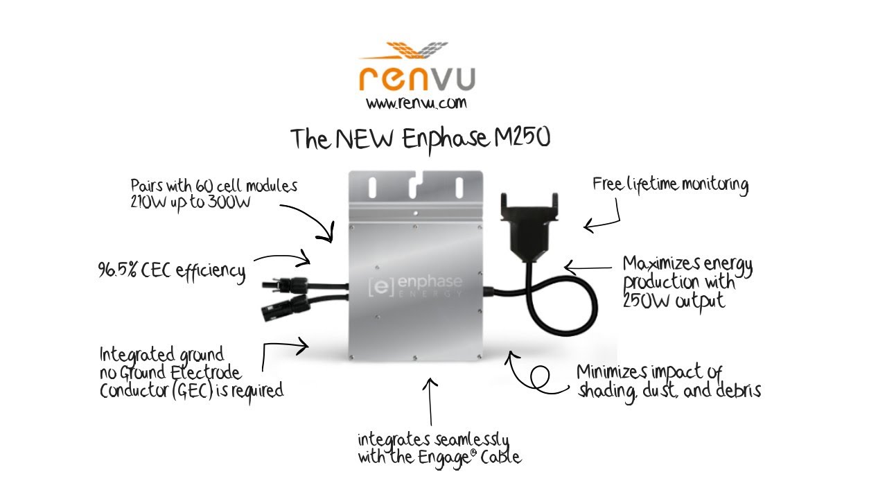
Enphase Microinverter Installation and Operation. © Enphase Energy. All rights reserved.
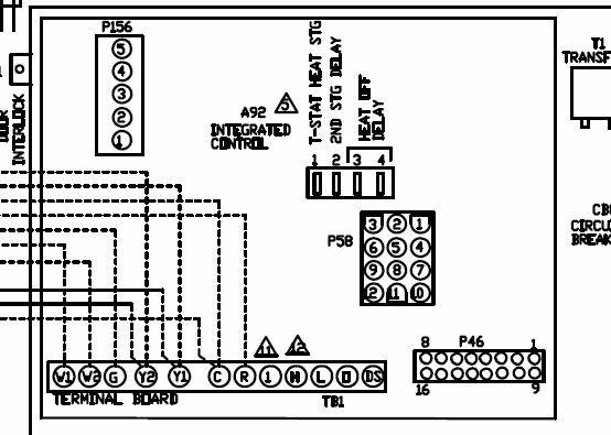
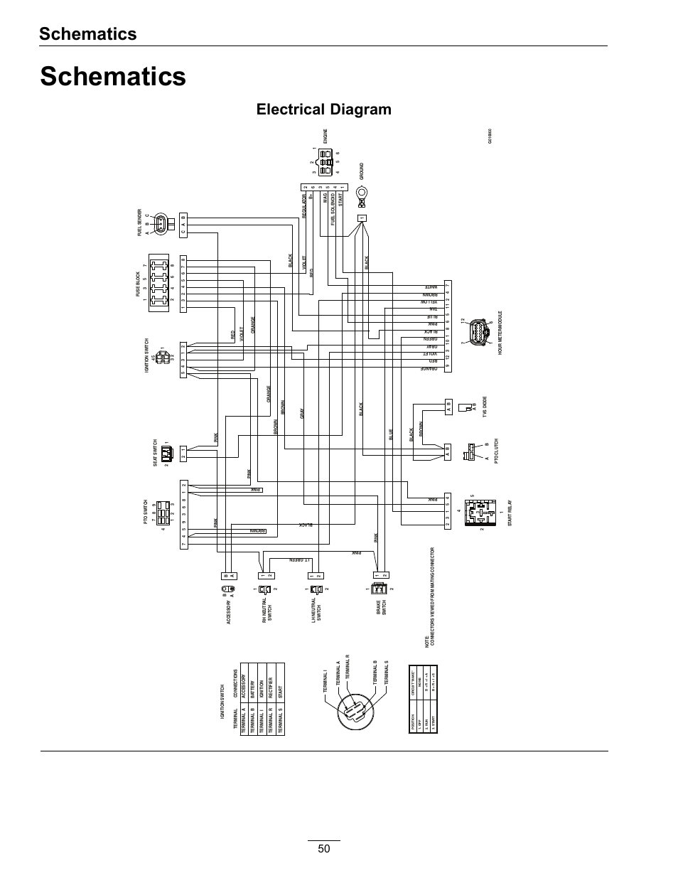
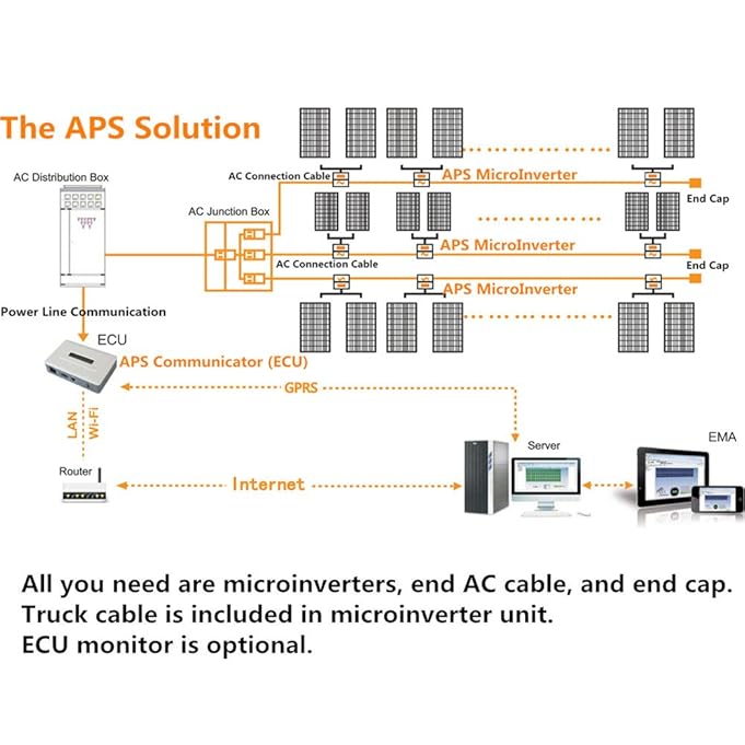
Sample Wiring Diagram – VAC, Single-Phase. Covers the details of wiring a grid-tie PV system. The Enphase wiring diagram is here I did the wiring in this order: 1- The junction box at the.
and in the Enphase Envoy-S Installation and Operation Manual at: Do not install the CTs in a panel where they exceed 75% of the wiring space of any. Enphase Energy: Smart Solar & Clean Energy For Everyone.
User documentation is updated frequently; Check the Enphase website Refer to the wiring diagram located in the Appendix of this manual for more.markings in the technical description and on the Enphase Micr oinverter System and the PV equipment. Connect the Enphase Microinverter to the utility grid only after receiving prior approval from the electrical utility company.
Be aware that the body of the Enphase Microinverter is . 2 Expedited Permit Process for PV Systems — Micro-Inverter Expedited Permit Process for Small-Scale PV Systems Micro-Inverter The information in this guideline is intended to help local jurisdictions and contractors identify when PV system installations are simple, needing only a basic review, and when an installation is more complex.
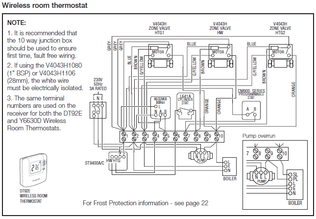
Collection of enphase micro inverter wiring diagram. A wiring diagram is a streamlined standard photographic representation of an electric circuit. It reveals the parts of the circuit as simplified forms, as well as the power and signal links in between the gadgets.
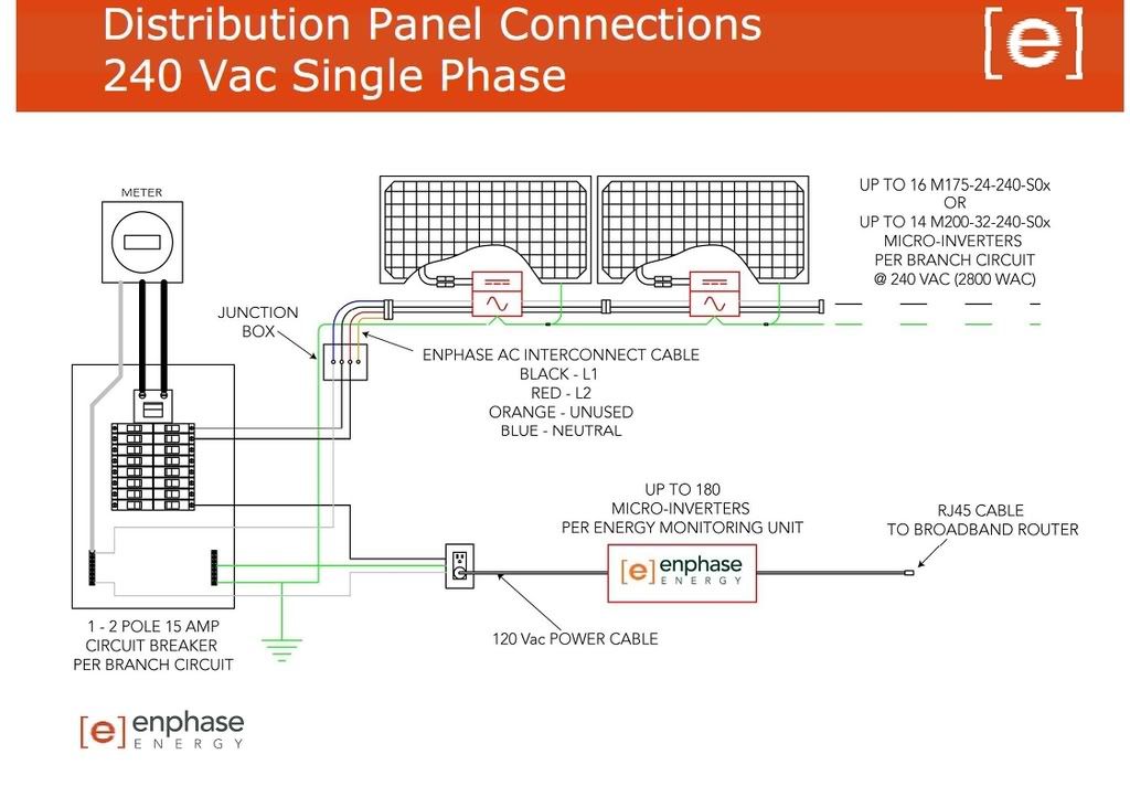
d c b a a 8 7 6 5 4 3 1 8 7 6 5 4 3 2 1 d c junction box neutral ground ac distribution panel or subpanel one 2-pole 20 amp circuit breaker per branch circuit. Engage Cable Installation 5 Enphase Energy Inc.
Rev 04 The Enphase Engage Cable and Accessories The Engage™ Cable is a continuous length of mm2 (12 AWG), outdoor-rated cable with integrated connectors for Enphase® Microinverters.Microinverters Make a Simple DIY Installation | Home Power MagazineDIY PV System Installation — Wiring