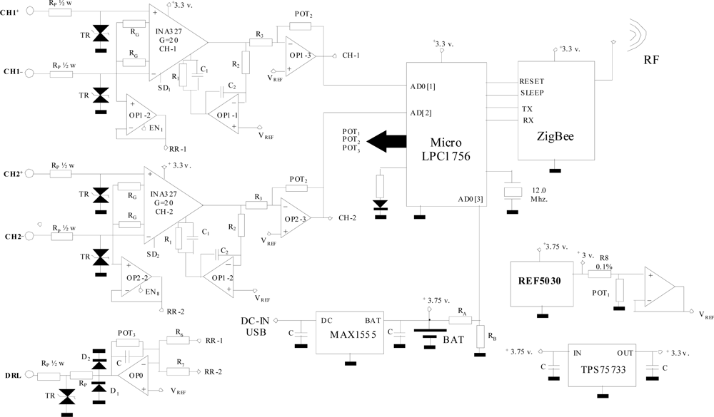
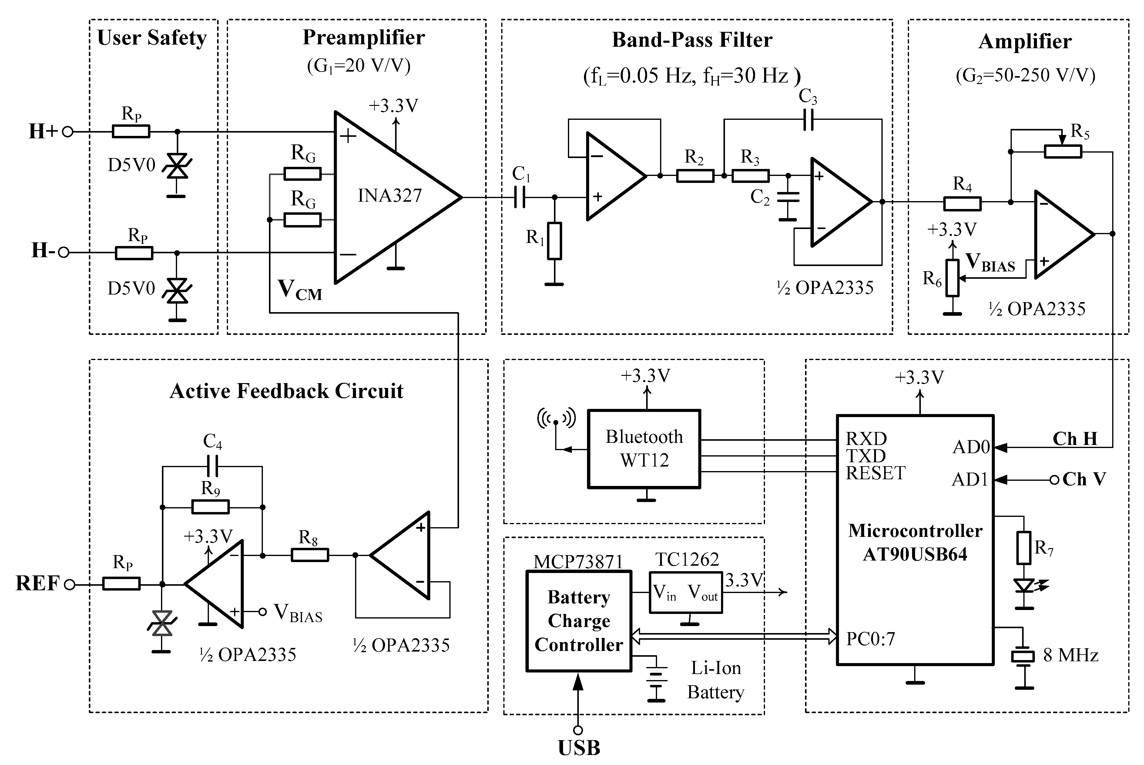
EOG measurement system for use in Human Computer/Machine . Analog circuit block diagram for forehead EOG measurement system.
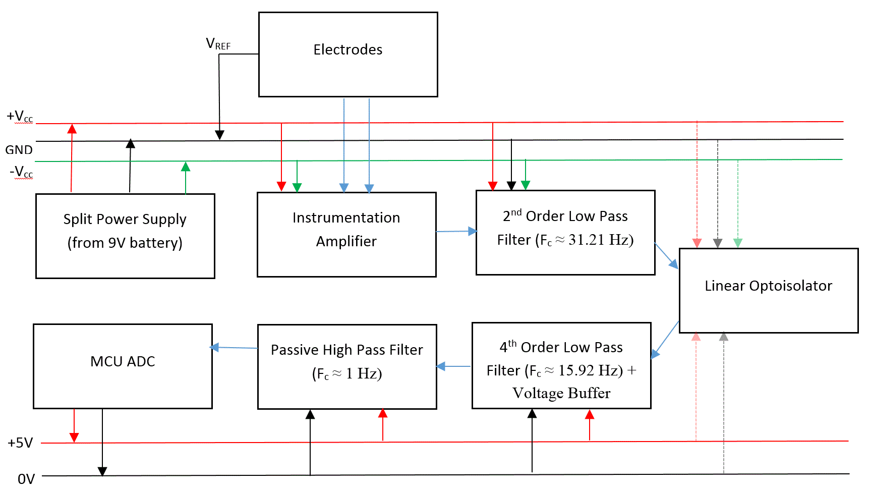
EOG being a voluntary biomedical signal, it can be used in HMI applications which make . System block diagram of EOG acquisition and conditioning circuit . The block diagram of purpose system is shown below: Fig Block Diagram of EOG acquisition circuit.
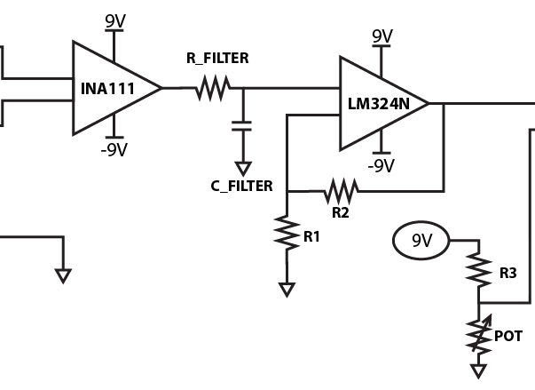
To generate EOG signal following amplifiers and filters. EOG measurement system for use in Human Computer/Machine .
Analog circuit block diagram for forehead EOG measurement system. The block diagram of purpose system is shown below: Fig Block Diagram of EOG acquisition circuit. To generate EOG signal following amplifiers and filters.Electrocardiography Circuit Design Nathan M Kesto 4/5/ 1 Abstract Electrocardiography (ECG) is the interpretation of the electrical activity of one’s heart over a period of time.
Recently, there has been increased interest and demand in. Eyeboard Electrooculography (EOG) System. For this and other electronics steps, refer to the schematic diagram.
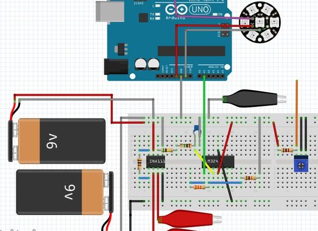
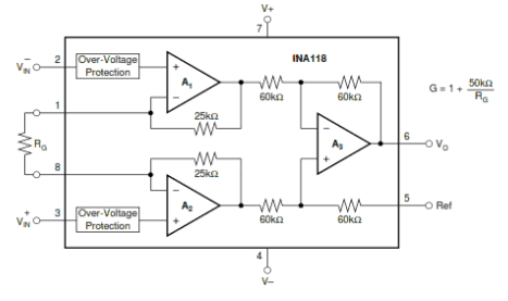
When working with such low voltages, amplification gain is needed, specially when working with bioelectrical signals. After the circuit is completed, you will need to connect the electrode to PINS 3, 2 and 5 of the INA Low Cost ElectroOculoGram Signals Amplifier.
Uploaded by. Block 2: Low-pass filter The low pass filter is a key element of this circuit. Due to the nature of EOG signals, the EOG bandwidth is from Hz to 50 Hz as the cutoff frequencies.

2 Fig. 2.
AD circuit diagram, where we can see the distribution of its pins, as well as its. The design of EMG-EOG signal conditioning system is divided into two modules, namely EMG conditioning module and EOG conditioning module.
The design of conditioning system consists of various units such as detection circuit, protection circuit, preamplifier, DC offset rejection filter, variable gain amplifier and filter as shown in Fig. 1.
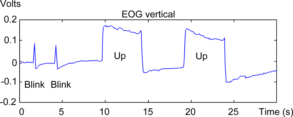
Fig EOG signal in both industrial applications and theoretical analysis is the design of existing biopotential amplifiers. Block Diagram of the DC drift suppression scheme used in the design of the novel EOG biopotential amplifier while maintaining circuit simplicity, effective management of fabrication cost and achieving perfect.Electrooculogram with an Arduino and a Computer.Electrooculogram with an Arduino and a Computer.