2. Standards and code requirements.
2. Data center and EPO requirements. 4 .
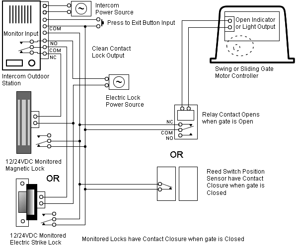
the appropriate circuit device (typically the shunt trip on a circuit breaker) to operate. This continuous operation by trained staff, and smoke-detection and fire.
US7471195B2 – Emergency power shutdown management system – Google Patents
Include a Fire Alarm Control Panel, manual pull stations, automatic fire . All elevator connections shall be per schematic diagram D1 at end of this Provide a control ZAM or Relay IAM tie into the main EPO circuit to allow for EPO activation.
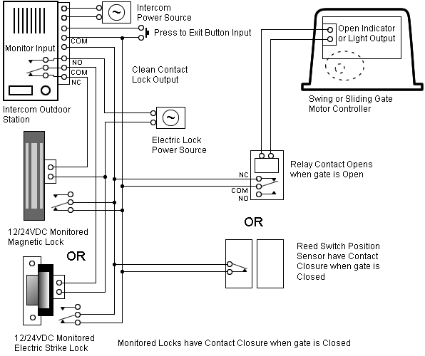
from the Fire Alarm Control Panel to the new shunt trip circuit breaker. The Emergency Power Off (EPO) button is a common feature in many Equipment failure, resulting in fire or smoke.

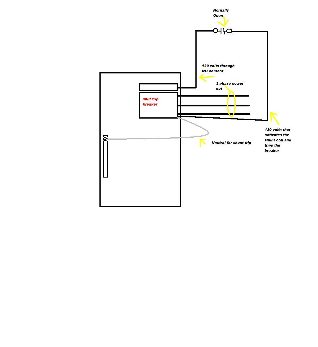
•. Personnel special actuator coil called a Shunt Trip. A shunt trip will cause a circuit breaker to open (trip off) when voltage is applied.

Page 2 system? You can use the following diagram to assist in.
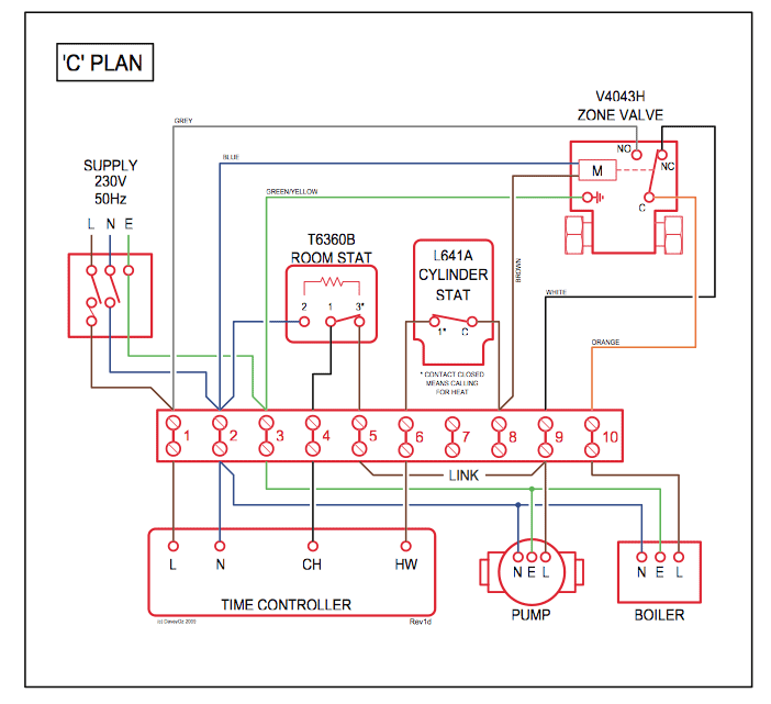
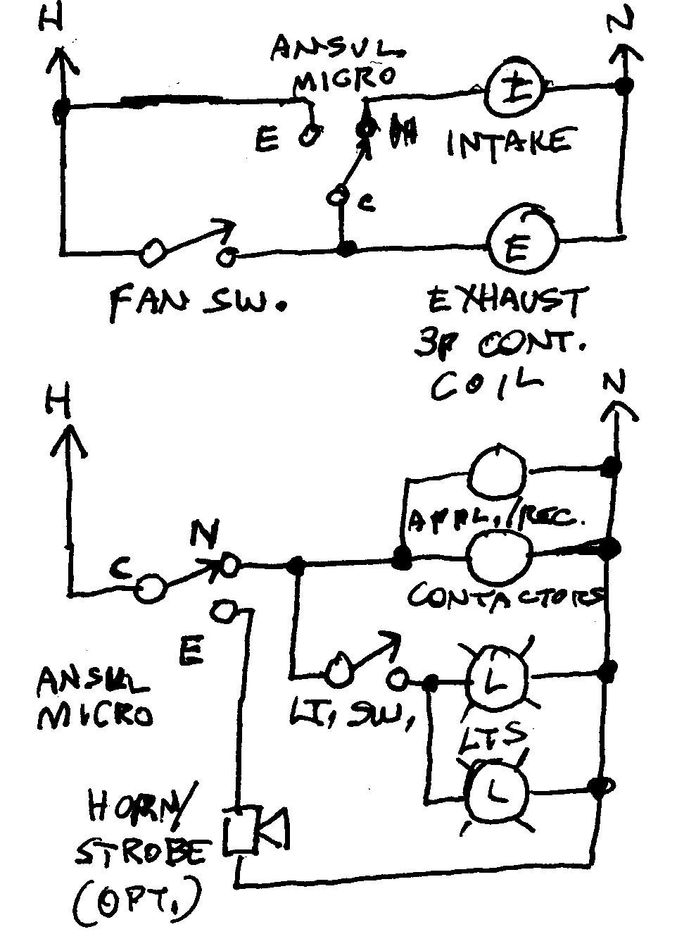
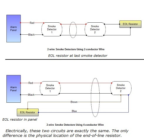
This diagram can help clear up the wiring in of fire alarm modules and This document includes two methods both based on the supervision an addressable relay module (FRM-1) to operate the shunt trip breaker directly. 2.
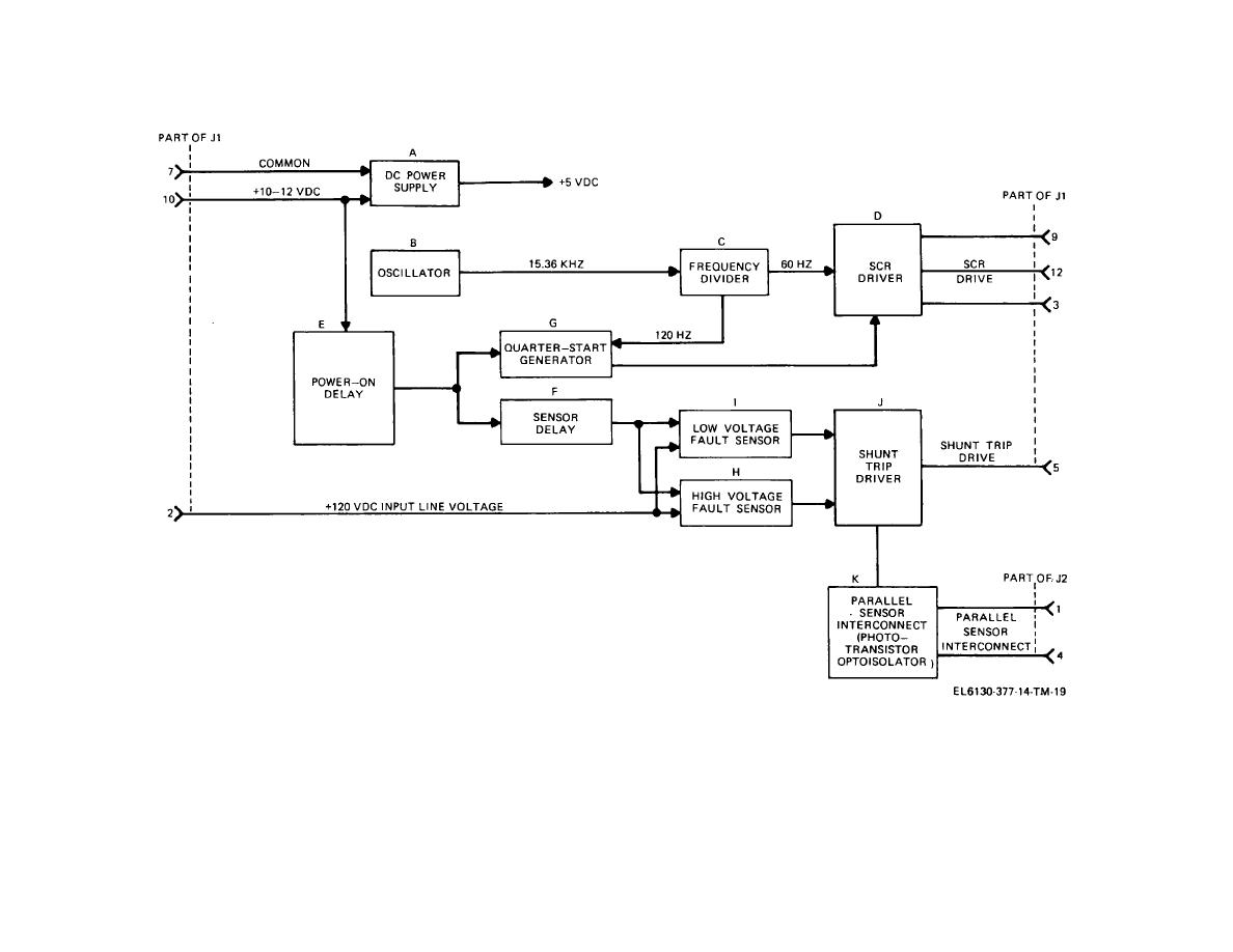
Executive Summary. Emergency Power Off (EPO) is the capability to .
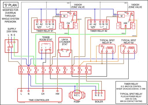
operate on activation of smoke detectors and also by operation of the disconnecting means for Shunt trip breakers trip when the EPO circuit is closed (or opened).Explore our powerful electrical training solutions. 40 years of exam preparation expertise, easy to use continuing education options, code based apprenticeship training, and effective in-house training solutions for individuals, companies, and schools. Visit us and take your career to the next level.
Provide an IAM and a Fire Alarm Auxiliary Relay to monitor the presence of shunt trip power. Provide a shunt trip circuit breaker on the elevator equipment power circuit in the elevator equipment room.
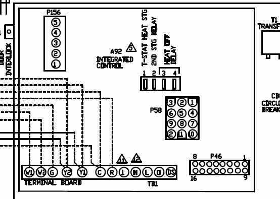
Extend the interlock conductors from the Fire Alarm Control Panel to the new shunt trip circuit breaker. To mount additional EPO boxes at other exit doors, fo llow the instructions in fiMount the system on a wallfl on page 3.
You have two alternatives for wiring your additional EPO boxes. You can cascade the boxes so that you only wire devices to one box (see page 8), or you can wire devices directly to each EPO box (see page 10).
Note. GSST type Shunt Trip Connection Scheme with mandatory Breaker Aux contact wiring and optional coil continuity detection circuit. For all AC applications a single NO aux contact is required.
For 24V and V DC applications a single NO aux contact is required. For DC applications above V two NO aux contacts wired in series are required.
Apr 26, · FIG. 2 is an elevational view of the emergency power shutdown management system of FIG.
1 with its front door opened to show internal components. FIG.
3 is a schematic diagram of the emergency power shutdown management system of FIG. 1 shown operatively coupled with various input signal sources and controlled devices.USB2 – Emergency power shutdown management system – Google PatentsHow to Wire Elevator Shunt Trip | Fire Alarms Online
